In this tutorial, we will learn about ESP32 I2C communication buses and how to perform master slave communication between two ESP32 development boards using ESP-IDF. We will use I2C driver to demonstrate I2C master (Host) and I2C slave (Device) communication between each other, whereby the master will send a message to the slave to toggle its onboard LED.
Before we move ahead, make sure you have the latest version of VS Code installed on your system with the ESP-IDF extension configured.
I2C Communication Introduction
I2C communication protocol is a 2-wire multi-master bus serial communication protocol which is used for short-range data transfer applications. It follows an asynchronous half-duplex serial communication protocol. Moreover, it requires only two wires to transfer data serially which are SCL and SDA lines. The SCL is the bidirectional clock line and the SDA is the bidirectional data line.
The I2C bus consists of multiple slave devices and multiple master devices. A device connected with the I2C bus can act as either a master or a slave. The master starts the data transfer process. Commonly there is one master that is controlling a single or multiple slaves connected with the same I2C bus through pull-up resistors. The slave devices are identified by their unique 7 bit address.
I2C Connection Between Devices
For SPI communication, both the devices are connected via a 2 wire interface. The serial clock line which is SCL is responsible for synchronizing the data transmission between the two wires. Whereas, the serial data line commonly referred to as SDA carries the data which is to be transmitted. One important thing to note here is that these lines are open-drain lines. Hence, if the devices are active low then these lines have to be connected to pull up resistors.
The diagram below illustrates a single master and multiple slaves connected with the same bus.

Another configuration can also be set up where there is a single slave which is being controlled by multiple masters.
ESP32 I2C Pins
The ESP32 development board comes with two I2C controllers also known as ports. These controllers manage I2C communication on the I2C bus. They can act as a master or slave.
The diagram below shows the default I2C pins present on ESP32 DevKit V1 board. As you may note, here the default I2C pin for SDA is GPIO21 and for SCL is GPIO22. You have the option to change them in code as well.

The I2C communication protocol is advantageous as it only requires two wires for data transfer or communication. Connecting with multiple devices simultaneously is also a plus point. However, this kind of communication protocol is only useful for short range data transfer.
Refer to the following article, for more information regarding I2C protocol:
ESP32 I2C Master Slave Communication with ESP-IDF
In this section, we will build and test a project using the I2C driver library for ESP-IDF. This project consists of two examples: master and slave which will be flashed on separate ESP32 boards. The boards will be connected with each other via the I2C communication pins that will be set in code. APIs for I2C driver will be used for both the master and slave programming. Both examples have to be uploaded to the respected ESP32 boards which are connected with each other, in order for the data transfer to occur vis I2C communication.
Use ESP32 as I2C Master with ESP-IDF
Open your VS Code and head over to View > Command Palette. Type ESP-IDF: New Project in the search bar and press enter.
Specify the project name and directory. We have named our project ‘ESP32_I2C_MASTER.’ For the ESP-IDF board, we have chosen the custom board option. For ESP-IDF target, we have chosen ESP32 module. Click ‘Choose Template’ button to proceed forward.

In the Extension, select ESP-IDF option:

We will click the ‘sample_project’ under the getting-started tab. Now click ‘Create project using sample_project.’

You will get a notification that the project has been created. To open the project in a new window, click ‘Yes.’
This opens our ESP32_I2C_MASTER project that we created, inside the EXPLORER tab. There are several folders inside our project folder. This is the same for every project which you will create through ESP-IDF Explorer. Lets head over to the main.c file. Go to main > main.c and open it. Copy the code given below in that file and save it.
ESP-IDF Code: I2C Master
#include <stdio.h>
#include <string.h>
#include "esp_log.h"
#include "driver/i2c.h"

static const char *TAG = "i2c-master";


#define I2C_MASTER_SCL_IO 22               /*!< gpio number for I2C master clock */
#define I2C_MASTER_SDA_IO 21               /*!< gpio number for I2C master data  */
#define I2C_MASTER_FREQ_HZ 100000        /*!< I2C master clock frequency */
#define I2C_MASTER_TX_BUF_DISABLE 0                           /*!< I2C master doesn't need buffer */
#define I2C_MASTER_RX_BUF_DISABLE 0                           /*!< I2C master doesn't need buffer */
#define SLAVE_ADDRESS 0x0A

#define WRITE_BIT I2C_MASTER_WRITE              /*!< I2C master write */
#define READ_BIT I2C_MASTER_READ                /*!< I2C master read */
#define ACK_CHECK_EN 0x1                        /*!< I2C master will check ack from slave*/
#define ACK_CHECK_DIS 0x0                       /*!< I2C master will not check ack from slave */
#define ACK_VAL 0x0                             /*!< I2C ack value */
#define NACK_VAL 0x1                            /*!< I2C nack value */

int i2c_master_port = 0;
static esp_err_t i2c_master_init(void)
{

    i2c_config_t conf = {
        .mode = I2C_MODE_MASTER,
        .sda_io_num = I2C_MASTER_SDA_IO,
        .sda_pullup_en = GPIO_PULLUP_ENABLE,
        .scl_io_num = I2C_MASTER_SCL_IO,
        .scl_pullup_en = GPIO_PULLUP_ENABLE,
        .master.clk_speed = I2C_MASTER_FREQ_HZ,
        // .clk_flags = 0,          /*!< Optional, you can use I2C_SCLK_SRC_FLAG_* flags to choose i2c source clock here. */
    };
    esp_err_t err = i2c_param_config(i2c_master_port, &conf);
    if (err != ESP_OK) {
        return err;
    }
    return i2c_driver_install(i2c_master_port, conf.mode, I2C_MASTER_RX_BUF_DISABLE, I2C_MASTER_TX_BUF_DISABLE, 0);
}

static esp_err_t i2c_master_send(uint8_t message[], int len)
{
    ESP_LOGI(TAG, "Sending Message = %s", message);

    esp_err_t ret;
    i2c_cmd_handle_t cmd = i2c_cmd_link_create();
    i2c_master_start(cmd);
    i2c_master_write_byte(cmd, SLAVE_ADDRESS << 1 | WRITE_BIT, ACK_CHECK_EN);
    i2c_master_write(cmd, message, len, ACK_CHECK_EN);
    i2c_master_stop(cmd);

    ret = i2c_master_cmd_begin(i2c_master_port, cmd, 1000 / portTICK_PERIOD_MS);
    i2c_cmd_link_delete(cmd);
    return ret;
}

void app_main(void)
{
    const uint8_t  on_command[] = "LED_ON";
    const uint8_t  off_command[] = "LED_OFF";
    ESP_ERROR_CHECK(i2c_master_init());
    ESP_LOGI(TAG, "I2C initialized successfully");

    while(1)
    {
        i2c_master_send(on_command, sizeof(on_command));
        vTaskDelay(1000/ portTICK_PERIOD_MS);
        i2c_master_send(off_command, sizeof(off_command));
        vTaskDelay(1000/ portTICK_PERIOD_MS);
    }

}
How the Code Works?
Firstly, we will start by including the necessary libraries that includes driver/i2c.h for the I2C communication and esp_log.h as the logging library to print informational logs etc.
#include <stdio.h>
#include <string.h>
#include "esp_log.h"
#include "driver/i2c.h"
This code uses Informational Logging. The log function takes in two arguments. The first argument is the tag and the second argument is a formatted string. Therefore this global variable will be useful while calling the ESP_LOGI() functions. Here, “i2c-master” is the tag that will be used while logging.
static const char *TAG = "i2c-master";Next, we have defined various parameters for the I2C master. This includes the SCL and SDA pins which will be used for I2C communication. Use these GPIO pins to connect the two ESP32 boards together. You may change these pins as well.
#define I2C_MASTER_SCL_IO 22               /*!< gpio number for I2C master clock */
#define I2C_MASTER_SDA_IO 21               /*!< gpio number for I2C master data  */
Moreover, other parameters include the I2C master clock frequency, slave address, Tx and Rx buffer disable, write bit, read bit etc.
#define I2C_MASTER_FREQ_HZ 100000        /*!< I2C master clock frequency */
#define I2C_MASTER_TX_BUF_DISABLE 0                           /*!< I2C master doesn't need buffer */
#define I2C_MASTER_RX_BUF_DISABLE 0                           /*!< I2C master doesn't need buffer */
#define SLAVE_ADDRESS 0x0A

#define WRITE_BIT I2C_MASTER_WRITE              /*!< I2C master write */
#define READ_BIT I2C_MASTER_READ                /*!< I2C master read */
#define ACK_CHECK_EN 0x1                        /*!< I2C master will check ack from slave*/
#define ACK_CHECK_DIS 0x0                       /*!< I2C master will not check ack from slave */
#define ACK_VAL 0x0                             /*!< I2C ack value */
#define NACK_VAL 0x1                            /*!< I2C nack value */
The I2C port number for the master is set as ‘0.’
int i2c_master_port = 0;Initializing I2C Master
The following function is responsible for initializing the I2C master.
static esp_err_t i2c_master_init(void)
{

    i2c_config_t conf = {
        .mode = I2C_MODE_MASTER,
        .sda_io_num = I2C_MASTER_SDA_IO,
        .sda_pullup_en = GPIO_PULLUP_ENABLE,
        .scl_io_num = I2C_MASTER_SCL_IO,
        .scl_pullup_en = GPIO_PULLUP_ENABLE,
        .master.clk_speed = I2C_MASTER_FREQ_HZ,
        // .clk_flags = 0,          /*!< Optional, you can use I2C_SCLK_SRC_FLAG_* flags to choose i2c source clock here. */
    };
    esp_err_t err = i2c_param_config(i2c_master_port, &conf);
    if (err != ESP_OK) {
        return err;
    }
    return i2c_driver_install(i2c_master_port, conf.mode, I2C_MASTER_RX_BUF_DISABLE, I2C_MASTER_TX_BUF_DISABLE, 0);
}
First, the parameters of the i2c_config_t structure are defined. This includes the mode of operation which is master in this case, the I2C communication pins, configure the internal pull-up resistors of ESP32 and setting the I2C clock speed.
i2c_config_t conf = {
        .mode = I2C_MODE_MASTER,
        .sda_io_num = I2C_MASTER_SDA_IO,
        .sda_pullup_en = GPIO_PULLUP_ENABLE,
        .scl_io_num = I2C_MASTER_SCL_IO,
        .scl_pullup_en = GPIO_PULLUP_ENABLE,
        .master.clk_speed = I2C_MASTER_FREQ_HZ,
        // .clk_flags = 0,          /*!< Optional, you can use I2C_SCLK_SRC_FLAG_* flags to choose i2c source clock here. */
    };
After the parameters are set, then the I2C configuration is initialized for the particular port. This is achieved by calling the function i2c_param_config() which takes in two parameters. The first parameter is the I2C port and the second parameter is the pointer to a constant configuration structure of type i2c_config_t. At this point, the I2C port gets configured.
esp_err_t err = i2c_param_config(i2c_master_port, &conf);The next step is to install the I2C driver. It takes in several parameters which are listed below:
- The I2C port number.
- The configuration mode that we set (master/slave)
- RX buffer disable. This is the receiving buffer size which is applicable for the slave.
- TX buffer disable. This is the sending buffer size which is also applicable for the slave.
- The last parameter is ‘intr_alloc_flags’ which is the flags for the allocated interrupt. It is ‘0’ in our case as we are not using interrupts in this example.
return i2c_driver_install(i2c_master_port, conf.mode, I2C_MASTER_RX_BUF_DISABLE, I2C_MASTER_TX_BUF_DISABLE, 0);Transmit
The function given below is responsible for sending data to the slave.
static esp_err_t i2c_master_send(uint8_t message[], int len)
{
    ESP_LOGI(TAG, "Sending Message = %s", message);

    esp_err_t ret;
    i2c_cmd_handle_t cmd = i2c_cmd_link_create();
    i2c_master_start(cmd);
    i2c_master_write_byte(cmd, SLAVE_ADDRESS << 1 | WRITE_BIT, ACK_CHECK_EN);
    i2c_master_write(cmd, message, len, ACK_CHECK_EN);
    i2c_master_stop(cmd);

    ret = i2c_master_cmd_begin(i2c_master_port, cmd, 1000 / portTICK_PERIOD_MS);
    i2c_cmd_link_delete(cmd);
    return ret;
}
We start off by creating and initializing the I2C command link using i2c_cmd_link_create() function. This function will return an I2C command link handler.
i2c_cmd_handle_t cmd = i2c_cmd_link_create(); After we create the command link, we will call i2c_master_start() and pass the command link as a parameter inside it. This will enable the I2C master to generate a starting signal. It will transmit all queued commands.
Note: This function is only called when the device acts as a master.
i2c_master_start(cmd);Then we call i2c_master_write_byte() function for the I2C master to write a single byte to the I2C bus. This function takes in three parameters. The I2C command link, I2C one byte command which will be written to the bus and the enable ack check for the master device.
Next, we call i2c_master_write() function for the I2C master to write the buffer to the I2C bus. This function takes in four parameters which are the I2C command link, the data to be transferred, the length of the data and enable ack check for the master device.
  i2c_master_write_byte(cmd, SLAVE_ADDRESS << 1 | WRITE_BIT, ACK_CHECK_EN);
  i2c_master_write(cmd, message, len, ACK_CHECK_EN);
Then we call the function i2c_master_cmd_begin() which will enable the I2C master to start sending the queued commands. This function takes in three parameters. The first parameter is the I2C port number, the second parameter is the I2C command handler and the third parameter is the maximum wait ticks which is set to 1 second in this case.
ret = i2c_master_cmd_begin(i2c_master_port, cmd, 1000 / portTICK_PERIOD_MS);Afterwards, we will free the command link when we are done sending the commands. This is achieved by calling the i2c_cmd_link() function and passing the I2C command handler as a parameter inside it.
i2c_cmd_link_delete(cmd);app_main()
Inside the app_main() function, we will first create two arrays that will hold the on_command and the off_command. The on_command[] holds the string “LED_ON” and the off_command[] holds the string “LED_OFF.” Then we call the function i2c_master_init() to initialize the I2C master. Inside the infinite loop, the master will continuously send the on_command and the off_command with a delay of 1 second in between the two commands by using the i2c_master_send() function that we previously defined.
void app_main(void)
{
    const uint8_t  on_command[] = "LED_ON";
    const uint8_t  off_command[] = "LED_OFF";
    ESP_ERROR_CHECK(i2c_master_init());
    ESP_LOGI(TAG, "I2C initialized successfully");

    while(1)
    {
        i2c_master_send(on_command, sizeof(on_command));
        vTaskDelay(1000/ portTICK_PERIOD_MS);
        i2c_master_send(off_command, sizeof(off_command));
        vTaskDelay(1000/ portTICK_PERIOD_MS);
    }

}
Compiling the Sketch
To flash your chip, type the following command in the serial terminal. Remember to replace the COM port with the one through which your board is connected.
idf.py -p COMX flash monitorAfter the code is successfully flashed, the terminal will print the on and off commands after every second.

Now let us setup the I2C receiver which will receive these commands and toggle its onboard LED as a result.
Use ESP32 as I2C Slave with ESP-IDF
Open your VS Code and head over to View > Command Palette. Type ESP-IDF: New Project in the search bar and press enter.
Specify the project name and directory. We have named our project ‘ESP32_SPI_SLAVE.’ For the ESP-IDF board, we have chosen the custom board option. For ESP-IDF target, we have chosen ESP32 module. Click ‘Choose Template’ button to proceed forward.

In the Extension, select ESP-IDF option:
We will click the ‘sample_project’ under the getting-started tab. Now click ‘Create project using sample_project.’
You will get a notification that the project has been created. To open the project in a new window, click ‘Yes.’
This opens our ESP32_I2C_SLAVE project that we created, inside the EXPLORER tab. There are several folders inside our project folder. This is the same for every project which you will create through ESP-IDF Explorer. Lets head over to the main.c file. Go to main > main.c and open it. Copy the code given below in that file and save it.
ESP-IDF Code: I2C Slave
#include <stdio.h>
#include <string.h>
#include "esp_log.h"
#include "driver/i2c.h"
#include "driver/gpio.h"

static const char *TAG = "i2c-slave";

#define LED_PIN 2

#define I2C_SLAVE_SCL_IO 22               /*!< gpio number for I2C master clock */
#define I2C_SLAVE_SDA_IO 21               /*!< gpio number for I2C master data  */
#define I2C_SLAVE_FREQ_HZ 100000        /*!< I2C master clock frequency */
#define I2C_SLAVE_TX_BUF_LEN 255                        /*!< I2C master doesn't need buffer */
#define I2C_SLAVE_RX_BUF_LEN 255                           /*!< I2C master doesn't need buffer */
#define ESP_SLAVE_ADDR 0x0A

#define WRITE_BIT I2C_MASTER_WRITE              /*!< I2C master write */
#define READ_BIT I2C_MASTER_READ                /*!< I2C master read */
#define ACK_CHECK_EN 0x1                        /*!< I2C master will check ack from slave*/
#define ACK_CHECK_DIS 0x0                       /*!< I2C master will not check ack from slave */
#define ACK_VAL 0x0                             /*!< I2C ack value */
#define NACK_VAL 0x1                            /*!< I2C nack value */

int i2c_slave_port = 0;
static esp_err_t i2c_slave_init(void)
{

    i2c_config_t conf_slave = {
    .sda_io_num = I2C_SLAVE_SDA_IO,          // select GPIO specific to your project
    .sda_pullup_en = GPIO_PULLUP_ENABLE,
    .scl_io_num = I2C_SLAVE_SCL_IO,          // select GPIO specific to your project
    .scl_pullup_en = GPIO_PULLUP_ENABLE,
    .mode = I2C_MODE_SLAVE,
    .slave.addr_10bit_en = 0,
    .slave.slave_addr = ESP_SLAVE_ADDR,      // address of your project
    .clk_flags = 0,
    };
    esp_err_t err = i2c_param_config(i2c_slave_port, &conf_slave);
    if (err != ESP_OK) {
        return err;
    }
    return i2c_driver_install(i2c_slave_port, conf_slave.mode, I2C_SLAVE_RX_BUF_LEN, I2C_SLAVE_TX_BUF_LEN, 0);
}

void app_main(void)
{
    uint8_t  received_data[I2C_SLAVE_RX_BUF_LEN] = {0};
    uint8_t  on_command[] = "LED_ON";

    gpio_pad_select_gpio(LED_PIN);
    gpio_set_direction(LED_PIN, GPIO_MODE_OUTPUT);

    ESP_ERROR_CHECK(i2c_slave_init());
    ESP_LOGI(TAG, "I2C Slave initialized successfully");

    while(1)
    {
    i2c_slave_read_buffer(i2c_slave_port, received_data, I2C_SLAVE_RX_BUF_LEN, 100 / portTICK_PERIOD_MS);
    i2c_reset_rx_fifo(i2c_slave_port);

    if(strncmp((const char*)received_data, "LED_ON", 6) == 0)
    {
    ESP_LOGI(TAG, "Data Recived = %s", received_data);
    gpio_set_level(LED_PIN, 1);
    }
    else if(strncmp((const char*)received_data, "LED_OFF", 7) == 0)
    {
    ESP_LOGI(TAG, "Data Recived = %s", received_data);
    gpio_set_level(LED_PIN, 0);
    }

    memset(received_data, 0, I2C_SLAVE_RX_BUF_LEN);
    }

}
How the Code Works?
Firstly, we will start by including the necessary libraries that includes driver/i2c.h for the I2C communication, esp_log.h as the logging library to print informational logs and driver/gpio.h library for the digital output pins of ESP32 etc.
#include <stdio.h>
#include <string.h>
#include "esp_log.h"
#include "driver/i2c.h"
#include "driver/gpio.h"
Here, “i2c-slave” is the tag that will be used while logging.
static const char *TAG = "i2c-slave";The on-board LED of ESP32 is connected at GPIO2. Therefore, we will define a variable called ‘LED_PIN’ that will hold the GPIO2. This will be used later on in the code to control the LED according to the message sent by the master.
#define LED_PIN 2Next, we have defined various parameters for the I2C slave. This includes the SCL and SDA pins which will be used for I2C communication. Use these GPIO pins to connect the two ESP32 boards together. These are the same pins we configured as I2C pins for the ESP32 master previously.
#define I2C_SLAVE_SCL_IO 22               /*!< gpio number for I2C master clock */
#define I2C_SLAVE_SDA_IO 21               /*!< gpio number for I2C master data  */
Moreover, other parameters include the I2C slave clock frequency, slave address, Tx and Rx buffer length, write bit, read bit etc.
#define I2C_SLAVE_FREQ_HZ 100000        /*!< I2C master clock frequency */
#define I2C_SLAVE_TX_BUF_LEN 255                        /*!< I2C master doesn't need buffer */
#define I2C_SLAVE_RX_BUF_LEN 255                           /*!< I2C master doesn't need buffer */
#define ESP_SLAVE_ADDR 0x0A

#define WRITE_BIT I2C_MASTER_WRITE              /*!< I2C master write */
#define READ_BIT I2C_MASTER_READ                /*!< I2C master read */
#define ACK_CHECK_EN 0x1                        /*!< I2C master will check ack from slave*/
#define ACK_CHECK_DIS 0x0                       /*!< I2C master will not check ack from slave */
#define ACK_VAL 0x0                             /*!< I2C ack value */
#define NACK_VAL 0x1                            /*!< I2C nack value */
The I2C port number for the slave is set as ‘0.’
int i2c_slave_port = 0;Initializing I2C Slave
The following function is responsible for initializing the I2C slave.
static esp_err_t i2c_slave_init(void)
{

    i2c_config_t conf_slave = {
    .sda_io_num = I2C_SLAVE_SDA_IO,          // select GPIO specific to your project
    .sda_pullup_en = GPIO_PULLUP_ENABLE,
    .scl_io_num = I2C_SLAVE_SCL_IO,          // select GPIO specific to your project
    .scl_pullup_en = GPIO_PULLUP_ENABLE,
    .mode = I2C_MODE_SLAVE,
    .slave.addr_10bit_en = 0,
    .slave.slave_addr = ESP_SLAVE_ADDR,      // address of your project
    .clk_flags = 0,
    };
    esp_err_t err = i2c_param_config(i2c_slave_port, &conf_slave);
    if (err != ESP_OK) {
        return err;
    }
    return i2c_driver_install(i2c_slave_port, conf_slave.mode, I2C_SLAVE_RX_BUF_LEN, I2C_SLAVE_TX_BUF_LEN, 0);
}
First, the parameters of the i2c_config_t structure are defined. This includes the mode of operation which is slave in this case, the I2C communication pins, configure the internal pull-up resistors of ESP32, slave address etc.
i2c_config_t conf_slave = {
    .sda_io_num = I2C_SLAVE_SDA_IO,          // select GPIO specific to your project
    .sda_pullup_en = GPIO_PULLUP_ENABLE,
    .scl_io_num = I2C_SLAVE_SCL_IO,          // select GPIO specific to your project
    .scl_pullup_en = GPIO_PULLUP_ENABLE,
    .mode = I2C_MODE_SLAVE,
    .slave.addr_10bit_en = 0,
    .slave.slave_addr = ESP_SLAVE_ADDR,      // address of your project
    .clk_flags = 0,
    };
After the parameters are set, then the I2C configuration is initialized for the particular port. This is achieved by calling the function i2c_param_config() which takes in two parameters. The first parameter is the I2C port and the second parameter is the pointer to a constant configuration structure of type i2c_config_t. At this point, the I2C port gets configured for the slave.
esp_err_t err = i2c_param_config(i2c_slave_port, &conf_slave);The next step is to install the I2C driver. It takes in several parameters which are listed below:
- The I2C port number.
- The configuration mode that we set which is slave in this case.
- RX buffer length. This is the receiving buffer size which is applicable for the slave only.
- TX buffer length. This is the sending buffer size which is applicable for the slave only.
- The last parameter is ‘intr_alloc_flags’ which is the flags for the allocated interrupt. It is ‘0’ in our case as we are not using interrupts in this example.
return i2c_driver_install(i2c_slave_port, conf_slave.mode, I2C_SLAVE_RX_BUF_LEN, I2C_SLAVE_TX_BUF_LEN, 0);app_main()
Inside the app_main() function, we will first create an array of size “I2C_SLAVE_RX_BUF_LEN” that will store the received data.
uint8_t received_data[I2C_SLAVE_RX_BUF_LEN] = {0};Then, we will configure the LED_PIN as a GPIO. To do that, we will use the gpio_pad_select_gpio() function. Specify the LED_PIN as a parameter inside this function. Then, we will set the direction of the pin as an output using the gpio_set_direction() function. This function takes in two arguments. The first argument is the GPIO pin and the second argument is the mode (input or output) we want to set the pin in. In our case, we want to set the LED_PIN as an output pin.
 gpio_pad_select_gpio(LED_PIN);
 gpio_set_direction(LED_PIN, GPIO_MODE_OUTPUT);
Then we call the function i2c_slave_init() to initialize the I2C slave.
   ESP_ERROR_CHECK(i2c_slave_init());
   ESP_LOGI(TAG, "I2C Slave initialized successfully");
Inside the infinite loop, firstly the I2C slave will read the data from internal buffer using the function i2c_slave_read_buffer(). The internal buffer saves the received data which can then be read. This function takes in four parameters. The first parameter is the port number. The second parameter is the array which stores the received data from the internal buffer. The third parameter is the size of the data that will be read. In this case, it is the receiving buffer length. The fourth parameter is the maximum waiting ticks which is set as 1 second in this case.
i2c_slave_read_buffer(i2c_slave_port, received_data, I2C_SLAVE_RX_BUF_LEN, 100 / portTICK_PERIOD_MS);Then, we will reset the I2C RX FIFO by calling the function i2c_reset_rx_fifo(). This function takes in a single parameter which is the I2C port number.
i2c_reset_rx_fifo(i2c_slave_port);We will use if-else-if condition to check the received string. If the received string matches “LED_ON” then the onboard LED will turn ON by setting the level of the LED_PIN to 1. Likewise, if the received string matches “LED_OFF” then the onboard LED will turn OFF by setting the level of the LED_PIN to 0. The serial terminal will also display the received message continuously.
  if(strncmp((const char*)received_data, "LED_ON", 6) == 0)
    {
    ESP_LOGI(TAG, "Data Recived = %s", received_data);
    gpio_set_level(LED_PIN, 1);
    }
    else if(strncmp((const char*)received_data, "LED_OFF", 7) == 0)
    {
    ESP_LOGI(TAG, "Data Recived = %s", received_data);
    gpio_set_level(LED_PIN, 0);
    }

    memset(received_data, 0, I2C_SLAVE_RX_BUF_LEN);
Compiling the Sketch
To flash your chip, type the following command in the serial terminal. Remember to replace the COM port with the one through which your board is connected.
idf.py -p COMX flash monitorIn our case, the master ESP32 board is connected with COM5 and the slave ESP32 board is connected with COM14.
Connect both the ESP32 boards with the I2C communication pins defined in code. Follow the table below to connect the master and slave boards together.
| ESP32 Master | ESP32 Slave | |
|---|---|---|
| SDA | GPIO21 | GPIO21 |
| SCL | GPIO22 | GPIO22 |
| GND | GND |

This is the output we get on the slave ESP32 terminal:
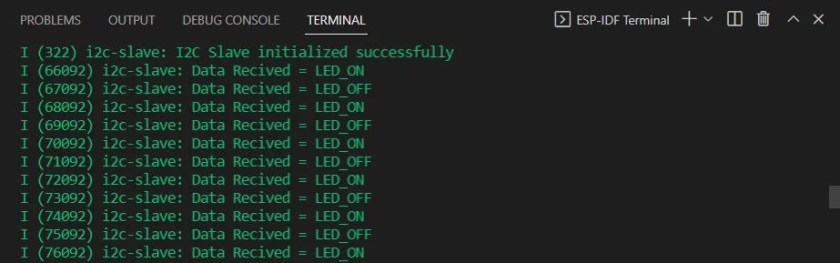
The slave ESP32 continuously receives LED_ON and LED_OFF commands with a delay of 1 second in between them. This causes its onboard LED connected with GPIO2, to toggle every second.
If you are using Arduino IDE instead of esp-idf, you can refer to this guide:
You may also like to read:
- ESP32 SPI Master Slave Communication with ESP-IDF
- ESP32 UART Communication using ESP-IDF
- ESP-IDF ESP32 Deep Sleep Modes and Wake up Sources
- ESP32 Web Server with ESP-IDF
- ESP32 Pulse Counter PCNT with ESP-IDF and Rotary Encoder Example
We are a team of experienced Embedded Software Developers with skills in developing Embedded Linux, RTOS, and IoT products from scratch to deployment with a demonstrated history of working in the embedded software industry. Contact us for your projects: admin@esp32tutorials.com
Hey, I am working on the I2S with Max98357A ic and try to play some audio files. I am facing some issue with the i2s. can you provide me an example code for audio.