In this ESP32 ESP-IDF tutorial, we will look at UART communication ports of ESP32. Firstly, we will discuss some important UART driver library provided in ESP-IDF and then demonstrate example projects to transmit and receive data over UART. Through the example project we will learn how configure the UART settings and install UART driver to read/write using the UART interface. The serial port (UART) are also used to debug and program ESP32 using a USB port.
Before we move ahead, make sure you have the latest version of VS Code installed on your system with the ESP-IDF extension configured.
UART Introduction
UART communication also known as Universal Asynchronous Receive Transmit or Serial communication is one of the simplest and commonly used communication protocols used between two devices. Data transfer between the two devices is via transmission and receiving lines which are connected with the two devices. Data is transferred in the form of bits from one device to another, bit by bit. One of the key advantages of using this communication protocol is that the two devices which are communicating need not be at the same operating frequency. However, it is necessary to se the same baud rate for both the devices in order for the instructions to be understood by them.
The ESP32 development consists of three UART ports commonly referred as UART0, UART1, and UART2. These three serial interfaces are hardware supported and work at 3.3V TTL level. Each of them exposes 4 pins: RX, TX, RTS and CTS.
ESP32 UART ESP-IDF APIs
Now let us discuss the UART driver library and its functions provided by ESP-IDF to establish communication between UART devices such as ESP32 and USB-TTL converter.
ESP-IDF provides driver/uart.h library that is required for UART communication. Let’s show you the steps using the API provided by this library to successfully setup UART communication.
This is the header file that is required to include the UART driver:
#include "driver/uart.h"Set Communication Parameters
The first step is to setup the UART communication parameters. These include the following:
- Baud Rate
- Data Bits
- Parity Control
- Number of stop Bits
- Hardware Flow Control Mode
- Communication Mode
There are generally two methods to set these communication methods.
In the first method which is more commonly used, we configure all the parameters in a single step. This is done by first creating a structure uart_config_t that contains all the definitions of the required parameters. And then calling the function uart_param_config() which takes in the UART port and the above structure as parameters inside it. This will configure the UART parameters.
const uart_port_t uart_num = UART_NUM_2;
uart_config_t uart_config = {
    .baud_rate = 115200,
    .data_bits = UART_DATA_8_BITS,
    .parity = UART_PARITY_DISABLE,
    .stop_bits = UART_STOP_BITS_1,
    .flow_ctrl = UART_HW_FLOWCTRL_CTS_RTS,
    .rx_flow_ctrl_thresh = 122,
};
// Configure UART parameters
ESP_ERROR_CHECK(uart_param_config(uart_num, &uart_config));
The second method involves calling separate functions to configure each of the parameters. The table below shows the parameters and their corresponding configuration functions.
| Baud Rate | uart_set_baudrate() |
| Number of Transmitted Bits | uart_set_word_length() selected out of uart_word_length_t |
| Parity Control | uart_set_parity() selected out of uart_parity_t |
| Number of Stop Bits | uart_set_stop_bits() selected out of uart_stop_bits_t |
| Hardware Flow Control Mode | uart_set_hw_flow_ctrl() selected out of uart_hw_flowcontrol_t |
| Communication Mode | uart_set_mode() selected out of uart_mode_t |
Set Communication Pins
In this step, we assign the physical pins that will allow UART communication to establish between two devices by connecting them.
The uart_set_pin() function is called to set the TX, RX, RTS and CTS pins which we pass as parameters inside it. This function takes in five parameters. The first parameter is the UART port number. The second parameter is the GPIO pin that we want to set up as the TX pin. The third parameter is the GPIO pin that we want to set up as the RX pin. Likewise, the fourth parameter is the GPIO pin that we want to set up as the RTS pin. Finally, the last parameter is the GPIO pin that we want to set up as the CTS pin. The driver will route the GPIO pins that we specify to the respective TX, RX, RTS and CTS signals.
esp_err_t uart_set_pin(uart_port_t uart_num, int tx_io_num, int rx_io_num, int rts_io_num, int cts_io_num)In the following function, we are setting GPIO4 as TX, GPIO5 as RX, GPIO18 as RTS and GPIO19 as CTS, for UART2.
ESP_ERROR_CHECK(uart_set_pin(UART_NUM_2, 4, 5, 18, 19));Install Driver
Next, we assign the resources of ESP32 for the UART driver. This stage marks the completion of the UART configuration. We use the function, uart_driver_install() to assign the necessary internal resources for the UART driver. It takes in five parameters. The first parameter is the UART port number. The rest of the parameters are listed below in order:
- rx_buffer_size (Size of RX ring buffer)
- tx_buffer_size (Size of TX ring buffer)
- queue_size (UART event queue size)
- uart_queue (UART event queue handle)
- intr_alloc_flags (Flags to allocate an interrupt)
esp_err_t uart_driver_install(uart_port_t uart_num, int rx_buffer_size, int tx_buffer_size, int queue_size, QueueHandle_t *uart_queue, int intr_alloc_flags)First we setup UART buffered IO with event queue as follows:
const int uart_buffer_size = (1024 * 2);
QueueHandle_t uart_queue;
Next, we install the driver by using the event queue:
ESP_ERROR_CHECK(uart_driver_install(UART_NUM_2, uart_buffer_size, \
                                        uart_buffer_size, 10, &uart_queue, 0));
Send and Receive Data
This stage denotes the start of the UART operation. The UART controller has a finite state machine commonly known as FSM that controls the UART communication. The FSM takes care of all the process whereby the application just reads and writes data to a specific buffer. Lets look at each of these steps.
Transmission
To send data serially, we first write the data to the TX FIFO buffer. The FSM then serializes this data and sends it out. We use the function, uart_write_bytes() to write the data to the TX ring buffer first. When there is available space in the TX FIFO buffer, this data is shifted from the ring buffer to the FIFO buffer. This process occurs behind the scene through an interrupt service routine.
The uart_write_bytes() takes in three parameters. the first parameter is the UART port number. The second parameter is the address of the data buffer and the third parameter is the length of the data to be sent.
int uart_write_bytes(uart_port_t uart_num, const void *src, size_t size)Below you can view the code which shows how to use of this function to transmit the message ‘Welcome to esp32tutorials.’
char* message = "Welcome to esp32tutorials\n";
uart_write_bytes(uart_num, (const char*)message, strlen(message));
Reception
Likewise, to receive the data serially, the FSM first processes this incoming data and parallelizes it. It then writes the data to the RX FIFO buffer. Finally, this data is read from the RX FIFO buffer. To red the data already present in the RX FIFO buffer, we use the function uart_read_bytes(). This function takes in four parameters. The first parameter is the UART port number. The second parameter is the pointer to the buffer. The third parameter is the length of the data and the last parameter is the count in RTOS ticks.
int uart_read_bytes(uart_port_t uart_num, void *buf, uint32_t length, TickType_t ticks_to_wait)ESP-IDF UART Echo Example ESP-IDF
In this section, we will build and test a project using the UART driver described in the previously. We will use the UART Echo example provided by ESP-IDF. Through this example we will show you how to use UART interfaces. For demonstration, the data received on the configured UART will be echoed back to the sender.
Create Example Project
Open your VS Code and head over to View > Command Palette. Type ESP-IDF: New Project in the search bar and press enter.
Specify the project name and directory. We have named our project ‘ESP_IDF_UART_ECHO.’ For the ESP-IDF board, we have chosen the custom board option. For ESP-IDF target, we have chosen ESP32 module. Click ‘Choose Template’ button to proceed forward.

In the Extension, select ESP-IDF option:

We will click the ‘softAP’ under the uart tab. Now click ‘Create project using template uart_echo.’

You will get a notification that the project has been created. To open the project in a new window, click ‘Yes.’
This opens our ESP_IDF_UART_ECHO project that we created, inside the EXPLORER tab. There are several folders inside our project folder. This is the same for every project which you will create through ESP-IDF Explorer.
ESP-IDF SDK Configuration Editor
Lets first head over to the menuconfig. Click the icon shown below. It opens the ESP-IDF SDK Configuration Editor.

Scroll down and open the Echo Example Configuration for our project. Here we can set the UART configuration parameter according to our needs. This includes the UART port number, UART communication speed (baud rate), UART RX pin, UART TX pin and the stack size for the task. Here you can view that by default, ESP-IDF is using UART port number 2 (UART2), baud rate of 115200, RX pin as GPIO5, TX pin as GPIO4 and task stack size as 2048. You can alter these parameters and then click the Save button found at the top. We will leave the configuration settings as default.

Lets head over to the main.c file. The main folder contains the source code meaning the main.c file will be found here.
Now go to main > uart_echo_example_main.c and open it.
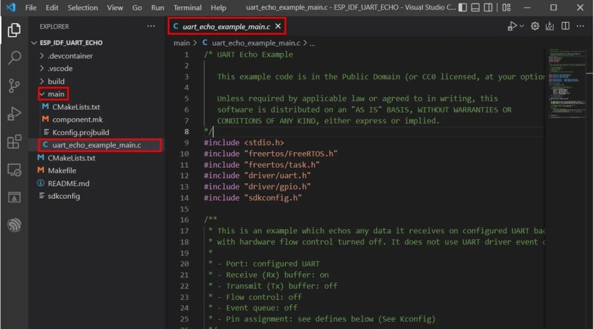
The following code opens up which is shown below. This example code will demonstrate UART Echo. It will echo the received message on UART2 back to the sender.
ESP-IDF Code: ESP32 UART Echo
/* UART Echo Example

   This example code is in the Public Domain (or CC0 licensed, at your option.)

   Unless required by applicable law or agreed to in writing, this
   software is distributed on an "AS IS" BASIS, WITHOUT WARRANTIES OR
   CONDITIONS OF ANY KIND, either express or implied.
*/
#include <stdio.h>
#include "freertos/FreeRTOS.h"
#include "freertos/task.h"
#include "driver/uart.h"
#include "driver/gpio.h"
#include "sdkconfig.h"

/**
 * This is an example which echos any data it receives on configured UART back to the sender,
 * with hardware flow control turned off. It does not use UART driver event queue.
 *
 * - Port: configured UART
 * - Receive (Rx) buffer: on
 * - Transmit (Tx) buffer: off
 * - Flow control: off
 * - Event queue: off
 * - Pin assignment: see defines below (See Kconfig)
 */

#define ECHO_TEST_TXD (CONFIG_EXAMPLE_UART_TXD)
#define ECHO_TEST_RXD (CONFIG_EXAMPLE_UART_RXD)
#define ECHO_TEST_RTS (UART_PIN_NO_CHANGE)
#define ECHO_TEST_CTS (UART_PIN_NO_CHANGE)

#define ECHO_UART_PORT_NUM      (CONFIG_EXAMPLE_UART_PORT_NUM)
#define ECHO_UART_BAUD_RATE     (CONFIG_EXAMPLE_UART_BAUD_RATE)
#define ECHO_TASK_STACK_SIZE    (CONFIG_EXAMPLE_TASK_STACK_SIZE)

#define BUF_SIZE (1024)

static void echo_task(void *arg)
{
    /* Configure parameters of an UART driver,
     * communication pins and install the driver */
    uart_config_t uart_config = {
        .baud_rate = ECHO_UART_BAUD_RATE,
        .data_bits = UART_DATA_8_BITS,
        .parity    = UART_PARITY_DISABLE,
        .stop_bits = UART_STOP_BITS_1,
        .flow_ctrl = UART_HW_FLOWCTRL_DISABLE,
        .source_clk = UART_SCLK_APB,
    };
    int intr_alloc_flags = 0;

#if CONFIG_UART_ISR_IN_IRAM
    intr_alloc_flags = ESP_INTR_FLAG_IRAM;
#endif

    ESP_ERROR_CHECK(uart_driver_install(ECHO_UART_PORT_NUM, BUF_SIZE * 2, 0, 0, NULL, intr_alloc_flags));
    ESP_ERROR_CHECK(uart_param_config(ECHO_UART_PORT_NUM, &uart_config));
    ESP_ERROR_CHECK(uart_set_pin(ECHO_UART_PORT_NUM, ECHO_TEST_TXD, ECHO_TEST_RXD, ECHO_TEST_RTS, ECHO_TEST_CTS));

    // Configure a temporary buffer for the incoming data
    uint8_t *data = (uint8_t *) malloc(BUF_SIZE);

    while (1) {
        // Read data from the UART
        int len = uart_read_bytes(ECHO_UART_PORT_NUM, data, BUF_SIZE, 20 / portTICK_RATE_MS);
        // Write data back to the UART
        uart_write_bytes(ECHO_UART_PORT_NUM, (const char *) data, len);
    }
}

void app_main(void)
{
    xTaskCreate(echo_task, "uart_echo_task", ECHO_TASK_STACK_SIZE, NULL, 10, NULL);
}
How the Code Works?
Firstly, we will start by including the necessary libraries that includes the FreeRTOS libraries to generate delays and create tasks, driver/gpio.h as we have to assign signals of a UART peripheral to ESP32 GPIO pins and driver/uart.h for the UART communication.
#include <stdio.h>
#include "freertos/FreeRTOS.h"
#include "freertos/task.h"
#include "driver/uart.h"
#include "driver/gpio.h"
#include "sdkconfig.h"
Then we have defined several variables including the RX, TX, RTS and CTS pins, baud rate, UAT port number and task stack size. These variables will access the values that we set in the menuconfig previously so the values are already defined.
#define ECHO_TEST_TXD (CONFIG_EXAMPLE_UART_TXD)
#define ECHO_TEST_RXD (CONFIG_EXAMPLE_UART_RXD)
#define ECHO_TEST_RTS (UART_PIN_NO_CHANGE)
#define ECHO_TEST_CTS (UART_PIN_NO_CHANGE)

#define ECHO_UART_PORT_NUM      (CONFIG_EXAMPLE_UART_PORT_NUM)
#define ECHO_UART_BAUD_RATE     (CONFIG_EXAMPLE_UART_BAUD_RATE)
#define ECHO_TASK_STACK_SIZE    (CONFIG_EXAMPLE_TASK_STACK_SIZE)
Moreover, we will define the Buffer size in this code. It is 1024 bytes or approximately 1 Kilobyte.
#define BUF_SIZE (1024)echo_task()
Next we have the function echo_task(). It consists of a uart_config_t structure that contains all the necessary parameters for UART communication. It will be later on passed as a parameter inside the uart_param_confg() function, when we configure the UART communication parameters. The configuration used is 8 data bits, no parity bit and 1 stop bit (8-N-1) with the baud rate of 115200. Moreover, the UART source clock is set to APB.
static void echo_task(void *arg)
{
    uart_config_t uart_config = {
        .baud_rate = ECHO_UART_BAUD_RATE,
        .data_bits = UART_DATA_8_BITS,
        .parity    = UART_PARITY_DISABLE,
        .stop_bits = UART_STOP_BITS_1,
        .flow_ctrl = UART_HW_FLOWCTRL_DISABLE,
        .source_clk = UART_SCLK_APB,
    };
Install Driver
Next, we call the uart_driver_install() function to install the UART driver. It takes in six parameters as described below:
- uart_port_t: This is the UART port number that we set up in menuconfig. We are using the default settings hence it is UART2 in our case.
- int rx_buffer_size: This is the size of the buffer which we defined as 1024 bytes multiplied by 2.
- int tx_buffer_size: This is the size of the TX buffer which is set to 0 in our case. This means that until all of the data is sent out, the driver will not use this buffer.
- int queue_size: This is the UART event queue size which is set to 0 as no queues are being used.
- QueueHandle_t *uart_queue: This is the UART event queue handle which is NULL in our case due to presence of no queues in this example.
- int intr_alloc_flags: This is the flag that is assigned to an interrupt. As we are not using interrupt in this example, hence it is set as NULL.
ESP_ERROR_CHECK(uart_driver_install(ECHO_UART_PORT_NUM, BUF_SIZE * 2, 0, 0, NULL, intr_alloc_flags));Configure UART Parameters
Next, we call the uart_param_config() function, to set the UART configuration parameters. It takes in two parameters. The first parameter is the UART port number and the second parameter is the UART parameter settings that we setup in the echo_task() function.
ESP_ERROR_CHECK(uart_param_config(ECHO_UART_PORT_NUM, &uart_config));Set Communication Pins
To set the UART communication (TX, RX, RTS and CTS) pins, we will use the uart_set_pin() function and specify the GPIOs as parameters inside it. In our case, the driver will allocate signals of TX, RX, RTS and CTS to the corresponding GPIO pins that we set respectively.
ESP_ERROR_CHECK(uart_set_pin(ECHO_UART_PORT_NUM, ECHO_TEST_TXD, ECHO_TEST_RXD, ECHO_TEST_RTS, ECHO_TEST_CTS));We will create a temporary buffer for the arriving data by allocating dynamic memory.
uint8_t *data = (uint8_t *) malloc(BUF_SIZE);Running UART Communication
Inside the while loop we will read data from UART2 by calling the uart_read_bytes() function and save it in the int variable ‘len.’ Then we will write this data (len) back to the UART using uart_write_bytes().
while (1) {
        int len = uart_read_bytes(ECHO_UART_PORT_NUM, data, BUF_SIZE, 20 / portTICK_RATE_MS);
        uart_write_bytes(ECHO_UART_PORT_NUM, (const char *) data, len);
    }
app_main()
Inside the main() function, we will create the task. To create a task, use the function xTaskCreate(). This function takes in several arguments.
- The first argument is the name of the function. In our case, we have set it to echo_task.
- The second argument is the name of the task for descriptive purposes. In our case we set the second argument as “uart_echo_task.”
- The third argument specifies the stack size of the task. This indicates the amount of memory we want to reserve for the particular task. We have set it to ‘2048’ which was the default value.
- The fourth argument is the parameter. It is a value that is passed as the parameter to the created task. This can be used to specify a variable that is being used in the main function and whose value needs to be added to the task. In our case, we will set this argument as NULL which indicates that we are not using this property.
- The fifth argument is the priority of the task. We have set it to ’10.’
- The last argument is the handle which is used to change the function of the task eg. suspend, delete, resume, get or set a config of task. This works as a pointer therefore the ampersand symbol is used with it. It is optional so we can also set it to NULL. In our case we have set it to NULL.
void app_main(void)
{
    xTaskCreate(echo_task, "uart_echo_task", ECHO_TASK_STACK_SIZE, NULL, 10, NULL);
}
Compiling the Sketch
To flash your chip, type the following command in the serial terminal. Remember to replace the COM port with the one through which your board is connected.
idf.py -p COMX flash monitor
After the code flashes successfully, connect your ESP32 with a USB to TTL converter. Use the following connections to connect both the devices together.
| USB-TTL converter | ESP32 |
| 3.3V | 3.3V |
| GND | GND |
| RX | GPIO4 (set up as TX) |
| TX | GPIO5 (set up as RX) |
After connecting the two devices together, plug the USB to TTL converter in your system. Now open the Device Manager > Ports and check the COM port to which it is connected. Note that it will be a different COM port than the one through which the ESP32 board is currently connected with. In our case the ESP32 is connected with COM5 and the USB to TTL converter is connected with COM14.
After finding out the port, you will have to open a serial terminal. We are using Putty. Set the connection type as serial, specify the COM port number and the baud rate. Then click Open.

The serial terminal will open for COM14. Now type any character from your keyboard and you will be able to view it in the terminal. If you disconnect TX or RX pin, the characters will stop printing. This suggests that the echo is coming from the ESP32 board. Here we sent the message ‘UART Echo Testing’.

ESP-IDF UART Asynchronous Rx Tx Tasks Example ESP-IDF
In this section, we will build and test another example project uart_async_rxtxtasks provided by ESP-IDF for UART. Through this example we will demonstrate two asynchronous tasks that use the same UART interface for the communication to take place. This example creates two FreeRTOS where the first task transmits a message ‘Hello world’ to the computer through UART after every 2 seconds. Whereas the second task reads the received data from UART and prints it.
Create Example Project
Open your VS Code and head over to View > Command Palette. Type ESP-IDF: New Project in the search bar and press enter.
Specify the project name and directory. We have named our project ‘ESP_IDF_UART_RxTxTasks.’ For the ESP-IDF board, we have chosen the custom board option. For ESP-IDF target, we have chosen ESP32 module. Click ‘Choose Template’ button to proceed forward.

In the Extension, select ESP-IDF option:
We will click the ‘uart_async_rxtxtasks’ under the uart tab. Now click ‘Create project using template uart_async_rxtxtasks.’

You will get a notification that the project has been created. To open the project in a new window, click ‘Yes.’
This opens our ESP_IDF_UART_RxTxTasks project that we created, inside the EXPLORER tab. Now go to main > uart_async_rxtxtasks_main.c and open it.

The following code opens up which is shown below.
ESP-IDF Code: ESP32 UART Async Rx Tx Tasks
/* UART asynchronous example, that uses separate RX and TX tasks

   This example code is in the Public Domain (or CC0 licensed, at your option.)

   Unless required by applicable law or agreed to in writing, this
   software is distributed on an "AS IS" BASIS, WITHOUT WARRANTIES OR
   CONDITIONS OF ANY KIND, either express or implied.
*/
#include "freertos/FreeRTOS.h"
#include "freertos/task.h"
#include "esp_system.h"
#include "esp_log.h"
#include "driver/uart.h"
#include "string.h"
#include "driver/gpio.h"

static const int RX_BUF_SIZE = 1024;

#define TXD_PIN (GPIO_NUM_4)
#define RXD_PIN (GPIO_NUM_5)

void init(void) {
    const uart_config_t uart_config = {
        .baud_rate = 115200,
        .data_bits = UART_DATA_8_BITS,
        .parity = UART_PARITY_DISABLE,
        .stop_bits = UART_STOP_BITS_1,
        .flow_ctrl = UART_HW_FLOWCTRL_DISABLE,
        .source_clk = UART_SCLK_APB,
    };
    // We won't use a buffer for sending data.
    uart_driver_install(UART_NUM_1, RX_BUF_SIZE * 2, 0, 0, NULL, 0);
    uart_param_config(UART_NUM_1, &uart_config);
    uart_set_pin(UART_NUM_1, TXD_PIN, RXD_PIN, UART_PIN_NO_CHANGE, UART_PIN_NO_CHANGE);
}

int sendData(const char* logName, const char* data)
{
    const int len = strlen(data);
    const int txBytes = uart_write_bytes(UART_NUM_1, data, len);
    ESP_LOGI(logName, "Wrote %d bytes", txBytes);
    return txBytes;
}

static void tx_task(void *arg)
{
    static const char *TX_TASK_TAG = "TX_TASK";
    esp_log_level_set(TX_TASK_TAG, ESP_LOG_INFO);
    while (1) {
        sendData(TX_TASK_TAG, "Hello world");
        vTaskDelay(2000 / portTICK_PERIOD_MS);
    }
}

static void rx_task(void *arg)
{
    static const char *RX_TASK_TAG = "RX_TASK";
    esp_log_level_set(RX_TASK_TAG, ESP_LOG_INFO);
    uint8_t* data = (uint8_t*) malloc(RX_BUF_SIZE+1);
    while (1) {
        const int rxBytes = uart_read_bytes(UART_NUM_1, data, RX_BUF_SIZE, 1000 / portTICK_RATE_MS);
        if (rxBytes > 0) {
            data[rxBytes] = 0;
            ESP_LOGI(RX_TASK_TAG, "Read %d bytes: '%s'", rxBytes, data);
            ESP_LOG_BUFFER_HEXDUMP(RX_TASK_TAG, data, rxBytes, ESP_LOG_INFO);
        }
    }
    free(data);
}

void app_main(void)
{
    init();
    xTaskCreate(rx_task, "uart_rx_task", 1024*2, NULL, configMAX_PRIORITIES, NULL);
    xTaskCreate(tx_task, "uart_tx_task", 1024*2, NULL, configMAX_PRIORITIES-1, NULL);
}
Compiling the Sketch
To flash your chip, type the following command in the serial terminal. Remember to replace the COM port with the one through which your board is connected.
idf.py -p COMX flash monitorAfter the code flashes successfully, connect your ESP32 with a USB to TTL converter. Use the following connections to connect both the devices together.
| USB-TTL converter | ESP32 |
| 3.3V | 3.3V |
| GND | GND |
| RX | GPIO4 (set up as TX) |
| TX | GPIO5 (set up as RX) |
After connecting the two devices together, plug the USB to TTL converter in your system. Now open the Device Manager > Ports and check the COM port to which it is connected. Note that it will be a different COM port than the one through which the ESP32 board is currently connected with. In our case, the ESP32 is connected with COM5 and the USB to TTL converter is connected with COM14.
After finding out the port, you will have to open a serial terminal. We are using RealTerm: Serial/TCP Terminal. You can download this program from this link (https://sourceforge.net/projects/realterm/).
Open COM14 and set the baud rate to 115200 and then click open.

The ESP-IDF terminal keeps logging the message ‘TX_TASK: Wrote 11 bytes’ which suggests that ESP32 is sending the message via UART after every 2 seconds. The COM14 terminal through which the USB-TTL converter is attached receives the message ‘Hello world’ after every 2 seconds.

Now let us send a message from the computer to ESP32. Here we are sending the message ‘Sending data to esp32’ from this terminal to ESP32.

The ESP32 receives the message and logs it in the ESP-IDF terminal as shown below:

You may also like to read:
- ESP32 GPIO with ESP-IDF with LED Blinking example
- ESP32 Push Button with ESP-IDF (Digital Input)
- ESP32 ADC with ESP-IDF Measure Analog Inputs
- ESP32 PWM ESP-IDF LED Brightness Control Example
- I2C LCD with ESP32 using ESP-IDF
- ESP32 ESP-IDF Connect with WiFi – Station Mode Example
- ESP32 Set an Access Point (AP) using ESP-IDF
We are a team of experienced Embedded Software Developers with skills in developing Embedded Linux, RTOS, and IoT products from scratch to deployment with a demonstrated history of working in the embedded software industry. Contact us for your projects: admin@esp32tutorials.com
Excellent article, but I would really like to see a picture of your ESP32 wiring.
Sure I will add the picture also.
ESP32’s default baud rate is 115200. If I change the baud rate more than that after building the project it’s again resetting it to 115200. As in config, it’s the maximum range of the baud rate. But the datasheet states it can go to 5mbps. Can anyone help how to set it up? I am using ESP32 DevkitCv4.
Hello Sir, i’m a student at university in Vietnam. Can you show me how the UART communication between the ESP32 devkit v1 and the Arduino Mega 2560 step by step?
it would be more helpful if u add bluetooth example with android app to send data from phone to esp32-idf ide and from esp32-idf ide to phone
We will post a article on it soon.