In this tutorial, we will learn to interface DS1307 RTC Module using ESP32 and ESP-IDF. This guide will include a brief description of the RTC module, connection with ESP32 board and then setting up a project in VS Code with ESP-IDF extension to acquire the current date/time and display it on the console.
Before we move ahead, make sure you have the latest version of VS Code installed on your system with the ESP-IDF extension configured.
DS1307 RTC Module Introduction
The DS1307 RTC module keeps track of the current date and time. It is used in electronics projects for time keeping, data logging, building clocks, timers etc. This module runs on the DS1307 RTC chip and also contains the 24C32 EEPRROM for accurate time keeping in terms of seconds, minutes, hours, days, and months. Moreover, time in both 12 hour and 24 hour format can be accessed through this module. It has a very accurate real time clock which houses a 32 kHz crystal oscillator.

On the backside, it possesses a 20mm 3V lithium coin cell holder which fits a CR2032 battery. This battery is extremely vital in tracking the time and making sure it stays correct in case the main power is cut off. Therefore, the CR2032 cell acts as a backup battery source incase the main power is lost.

DS1307 RTC Module Pinout
The diagram below shows the pinout of the DS1307 RTC module.

As you can see in the diagram above, the DS1307 module consists of a total of twelve pins but we only require pins 2 to 5 to access the current time using a single module. These include the I2C communication pins (SCL and SDA) and the power supply pins (VCC and GND).
| VCC | This is the power supply pin which is connected with Vin (5V) of ESP32. |
| GND | This is the ground pin |
| SCL | This is the serial clock pin which will produce the clock signal |
| SDA | This is the serial data pin which is used for sending and receiving data |
| DS | This pin outputs the temperature readings incase a DS18B20 temperature sensor is connected at U1 (backside) |
| SQ | This pin outputs square waves of different frequencies for example 1Hz, 4kHz, 8kHz, or 32kHz. |
| BAT | This is the backup power supply input (3-5V) for the CR2032 coil cell. This makes sure the time keeping stays accurate in case the main power fails. |
Specifications
Let us look at some key specifications of the DS1307 RTC module.
- Operating voltage of 4.5 – 5.5V
- Current consumption is less than 1.5mA
- 3V CR2032 Coin Cell as battery source
- Square wave output signal which is programmable
- Detects power failure automatically and switches circuitry accordingly
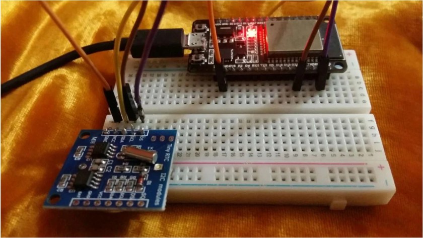
Interfacing DS1307 RTC Module with ESP32
We will need the following components to connect our ESP32 board with the DS1307 Module.
- ESP32 board
- DS1307 Module
- Connecting Wires
- Breadboard
The connection of DS1307 Module with the ESP32 board is straightforward as it just involves the connection of the 4 pins (GND, VCC, SDA, and SCL) with ESP32. We have to connect the VCC terminal with Vin pin, ground with the ground (common ground), SCL of the sensor with SCL of ESP32 board, and SDA of the sensor with the SDA pin of the ESP32 board. We will use the default I2C pins of ESP32 board to connect with the sensor module.
In ESP32, the default I2C pin for SDA is GPIO21 and for SCL is GPIO22.
The connections between the devices are specified in the table below:
| DS1307 Module | ESP32 |
|---|---|
| GND | GND |
| VCC | Vin |
| SDA | GPIO21(I2C SDA) |
| SCL | GPIO22 (I2C SCL) |

Real Time Clock with ESP32 using DS1307 Module and ESP-IDF
We will build and create a project in VS Code with ESP-IDF extension. The code will output the current date and time in the ESP-IDF terminal using the I2C device library, esp_idf_lib_helpers and ds1307.h. We will use ds1307 driver written by UncleRus.
Create Example Project
Open your VS Code and head over to View > Command Palette. Type ESP-IDF: New Project in the search bar and press enter.
Specify the project name and directory. We have named our project ‘DS1307_ESP32.’ For the ESP-IDF board, we have chosen the custom board option. For ESP-IDF target, we have chosen ESP32 module. Click ‘Choose Template’ button to proceed forward.
In the Extension, select ESP-IDF option:

We will click the ‘sample_project’ under the get-started tab. Now click ‘Create project using template sample_project.’

You will get a notification that the project has been created. To open the project in a new window, click ‘Yes.’
This opens the project that we created inside the EXPLORER tab. There are several folders inside our project folder. This is the same for every project which you will create through ESP-IDF Explorer.
- First, let’s add the necessary header files for the libraries required for this project. Create a new folder called ‘components’ and add the following three sub-folders under it:
- esp_idf_lib_helpers
- i2cdev
- ds1307
Add the ds1307, esp_idf_lib_helpers, and i2cdev folders in ‘components’ folder by copying from this link as listed below:

ESP32 DS1307 Display Current Time and Date Code
Now head over to the main.c file. The main folder contains the source code meaning the main.c file will be found here. Go to main > main.c and open it. Copy the code given below in that file and save it.
This is an example sketch for the driver ds1307. It continuously prints the current date and time in the ESP-IDF terminal.
#include <stdio.h>
#include <freertos/FreeRTOS.h>
#include <freertos/task.h>
#include <ds1307.h>
#include <string.h>

void ds1307_test(void *pvParameters)
{
    i2c_dev_t dev;
    memset(&dev, 0, sizeof(i2c_dev_t));

    ESP_ERROR_CHECK(ds1307_init_desc(&dev, 0, 21, 22));


    struct tm time = {
        .tm_year = 122, //(2022 - 1900)
        .tm_mon  = 12,
        .tm_mday = 13,
        .tm_hour = 17,
        .tm_min  = 05,
        .tm_sec  = 30
    };
    ESP_ERROR_CHECK(ds1307_set_time(&dev, &time));

    while (1)
    {
        ds1307_get_time(&dev, &time);

        printf("%04d-%02d-%02d %02d:%02d:%02d\n", time.tm_year + 1900 /*Add 1900 for better readability*/, time.tm_mon + 1,
            time.tm_mday, time.tm_hour, time.tm_min, time.tm_sec);

        vTaskDelay(pdMS_TO_TICKS(500));
    }
}

void app_main()
{
    ESP_ERROR_CHECK(i2cdev_init());

    xTaskCreate(ds1307_test, "ds1307_test", configMINIMAL_STACK_SIZE * 8, NULL, 5, NULL);
}
How the Code Works?
Firstly, we will start by including the necessary libraries for this project. This includes the ds1307 library to access the APIs for configuring and obtaining the current date/time and freertos libraries to create the task.
#include <stdio.h>
#include <freertos/FreeRTOS.h>
#include <freertos/task.h>
#include <ds1307.h>
#include <string.h>
ds1307_test()
Inside the ds1307_test() function, we first create an instance of i2c_dev_t struct which is used to configure and initialize the RTC module. After that we initialize all members of this struct to zero with memset.
    i2c_dev_t dev;
    memset(&dev, 0, sizeof(i2c_dev_t));
/**
 * I2C device descriptor
 */
typedef struct
{
    i2c_port_t port;         //!< I2C port number
    i2c_config_t cfg;        //!< I2C driver configuration
    uint8_t addr;            //!< Unshifted address
    SemaphoreHandle_t mutex; //!< Device mutex
    uint32_t timeout_ticks;  /*!< HW I2C bus timeout (stretch time), in ticks. 80MHz APB clock
                                  ticks for ESP-IDF, CPU ticks for ESP8266.
                                  When this value is 0, I2CDEV_MAX_STRETCH_TIME will be used */
} i2c_dev_t;
Next, the ds1307_init_desc() function initialize ds1307 device descriptor by passing dev struct, I2C port, ESP32 SDA pin and ESP32 SCL pin respectively.
ESP_ERROR_CHECK(ds1307_init_desc(&dev, 0, 21, 22));Next we define the parameters of the tm struct which we define as ‘time.’ Inside it we specify the current year, month, date, hour, minute and second. After that, we call ds1307_set_time() to initialize the date and time as defined in the time structure. This function basically sets the time to RTC.
   struct tm time = {
        .tm_year = 122, //(2022 - 1900)
        .tm_mon  = 12,
        .tm_mday = 13,
        .tm_hour = 17,
        .tm_min  = 05,
        .tm_sec  = 30
    };
    ESP_ERROR_CHECK(ds1307_set_time(&dev, &time));
Inside the while loop, we access the current date and time using ds1307_get_time() function. After every 0.5 second, we print the current date and time on the ESP-IDF terminal by accessing each member of the time structure.
    while (1)
    {
        ds1307_get_time(&dev, &time);

        printf("%04d-%02d-%02d %02d:%02d:%02d\n", time.tm_year + 1900 /*Add 1900 for better readability*/, time.tm_mon + 1,
            time.tm_mday, time.tm_hour, time.tm_min, time.tm_sec);

        vTaskDelay(pdMS_TO_TICKS(500));
    }
Compiling the Sketch
To flash your chip, type the following command in the serial terminal. Remember to replace the COM port with the one through which your board is connected.
idf.py -p COMX flash monitorAfter the code is successfully flashed, you can view the current date and time on the console.

You may also like to read:
- ESP32 ESP-IDF MQTT Publish BME680 Sensor Readings
- ESP32 ESP-IDF with MAX7219 Dot Matrix Display Module
- Interface OLED with ESP32 using ESP-IDF
- I2C LCD with ESP32 using ESP-IDF
We are a team of experienced Embedded Software Developers with skills in developing Embedded Linux, RTOS, and IoT products from scratch to deployment with a demonstrated history of working in the embedded software industry. Contact us for your projects: admin@esp32tutorials.com
Adding the folders to my project still doesnt let me use the ds1307 component