In this tutorial, we will build an ESP32 web server using ESP-IDF that will display DHT22 sensor readings. The DHT22 sensor is a widely used sensor to obtain temperature and humidity readings. The web server will act as a weather station by displaying temperature and humidity readings on the web page which will update after every 10 seconds. We will use VS Code with ESP-IDF extension to create and build this EP32 web server. It will be easily accessed on different devices such as laptops, mobiles, etc which are connected to the same Wi-Fi network as the ESP32 board.

We will program our ESP32 development board in VS Code with ESP-IDF extension. Before we move ahead, make sure you have the latest version of VS Code installed on your system with the ESP-IDF extension configured.
- Install ESP32 ESP-IDF on Windows
- Install ESP32 ESP-IDF on Linux Ubuntu
- Getting Started with ESP32 using ESP-IDF
ESP32 ESP-IDF DHT22 Web Server Overview
Our ESP32 will host a web server that serves the HTML/CSS files to a web client which is a web browser. We will create the web server with the help of the HTTP web server library available in esp-idf. When a user enters the IP address in a web browser, an HTTP get request is sent to ESP32. The ESP32 responds to the request by sending a buffer which contains the HTML and CSS files to build the webpage that displays the DHT22 sensor data.

Users can access the web server through an IP address and any web client application such as a web browser on your laptop or mobile phone.
Interfacing DHT22 with ESP32
DHT22 sensor (AM2302) is a simple, low priced temperature and humidity sensor that uses capacitive humidity sensor and a thermistor to calculate the sensor data in the surrounding atmosphere. This includes the relative humidity and the ambient temperature. It is a pre-calibrated sensor that outputs a calibrated digital output with a 1-wire protocol. Therefore, they are easily connected with the microcontrollers eg. ESP32 development boards using a single GPIO pin.
We will need the following components to connect our ESP32 board with the DHT22 sensor.
- ESP32 board
- DHT22 sensor
- 10k ohm resistor (not required if using the DHT22 sensor module)
- Breadboard
- Connecting Wires
The connections between the devices are specified in the table below:
| DHT22 Pin | ESP32 |
|---|---|
| 1 (Vcc) | The VCC pin will be connected with 3.3V or Vin pin of ESP32 board. |
| 2 (Data Out) | Any GPIO pin of the ESP32 board along with a 10k ohm pull-up resistor. We are using GPIO27 to connect with pin 2 along with the pull-up resistor. |
| 3 (NC) | This pin is not used. |
| 4 (GND) | Common ground with ESP32. |
Connect the DHT22 sensor with the ESP32 development board as shown in the schematic diagram below:

You can read this dedicated guide for DHT22:
- DHT22 with ESP32 ESP-IDF and Display Readings on OLED
- ESP32 MQTT Publish DHT22 Sensor Readings to Node-Red using ESP-IDF
ESP32 DHT22 Web Server with ESP-IDF
In this section, let us create the DHT22 Web Server using ESP-IDF. The ESP32 board will be set up in station mode, whereby it will connect to a Wi-Fi network through a router. After a successful connection with the AP, an IP address will be assigned to the board which will be used to access the web server.
Create Project
Open your VS Code and head over to View > Command Palette. Type ESP-IDF: New Project in the search bar and press enter.
Specify the project name, directory, and the ESP-IDF board and target. For the ESP-IDF board, we have chosen the custom board option. For ESP-IDF target, we have chosen ESP32 module. Click ‘Choose Template’ button to proceed forward.
In the Extension, select ESP-IDF option:

We will click the ‘sample_project’ under the get-started tab. Now click ‘Create project using template sample_project.’

You will get a notification that the project has been created. To open the project in a new window, click ‘Yes.’
This opens the project that we created inside the EXPLORER tab. There are several folders inside our project folder. This is the same for every project which you will create through ESP-IDF Explorer.
First, let’s add the necessary header files for the libraries required for this project. Create a new folder called ‘components/DHT22’ and add the following files listed below:
- DHT22.h
- DHT22.c
- CMakeLists.txt
We will use the DHT22 library provided by Andrey-m on GitHub.
Now head over to the main.c file. The main folder contains the source code meaning the main.c file will be found here. Go to main > main.c and open it. Copy the code given below in that file and save it.
ESP32 ESP-IDF DHT22 Web Server Code
#include <stdio.h>
#include <stdlib.h>
#include <string.h> //Requires by memset
#include "freertos/FreeRTOS.h"
#include "freertos/task.h"
#include "esp_system.h"
#include "esp_spi_flash.h"
#include <esp_http_server.h>

#include "esp_wifi.h"
#include "esp_event.h"
#include "freertos/event_groups.h"
#include "esp_log.h"
#include "nvs_flash.h"
#include "esp_netif.h"
#include "driver/gpio.h"
#include <lwip/sockets.h>
#include <lwip/sys.h>
#include <lwip/api.h>
#include <lwip/netdb.h>
#include "DHT22.h"
#define ESP_WIFI_SSID "PTCL-08"
#define ESP_WIFI_PASSWORD "44332211"
#define ESP_MAXIMUM_RETRY 5
static const char *TAG = "esp32 webserver";
/* FreeRTOS event group to signal when we are connected*/
static EventGroupHandle_t s_wifi_event_group;
/* The event group allows multiple bits for each event, but we only care about two events:
* - we are connected to the AP with an IP
* - we failed to connect after the maximum amount of retries */
#define WIFI_CONNECTED_BIT BIT0
#define WIFI_FAIL_BIT BIT1
static int s_retry_num = 0;
int wifi_connect_status = 0;
double temp;
double hum;
char html_page[] = "<!DOCTYPE HTML><html>\n"
"<head>\n"
" <title>ESP-IDF DHT22 Web Server</title>\n"
" <meta http-equiv=\"refresh\" content=\"10\">\n"
" <meta name=\"viewport\" content=\"width=device-width, initial-scale=1\">\n"
" <link rel=\"stylesheet\" href=\"https://use.fontawesome.com/releases/v5.7.2/css/all.css\" integrity=\"sha384-fnmOCqbTlWIlj8LyTjo7mOUStjsKC4pOpQbqyi7RrhN7udi9RwhKkMHpvLbHG9Sr\" crossorigin=\"anonymous\">\n"
" <link rel=\"icon\" href=\"data:,\">\n"
" <style>\n"
" html {font-family: Arial; display: inline-block; text-align: center;}\n"
" p { font-size: 1.2rem;}\n"
" body { margin: 0;}\n"
" .topnav { overflow: hidden; background-color: #241d4b; color: white; font-size: 1.7rem; }\n"
" .content { padding: 20px; }\n"
" .card { background-color: white; box-shadow: 2px 2px 12px 1px rgba(140,140,140,.5); }\n"
" .cards { max-width: 700px; margin: 0 auto; display: grid; grid-gap: 2rem; grid-template-columns: repeat(auto-fit, minmax(300px, 1fr)); }\n"
" .reading { font-size: 2.8rem; }\n"
" .card.temperature { color: #0e7c7b; }\n"
" .card.humidity { color: #17bebb; }\n"
" </style>\n"
"</head>\n"
"<body>\n"
" <div class=\"topnav\">\n"
" <h3>ESP-IDF DHT22 WEB SERVER</h3>\n"
" </div>\n"
" <div class=\"content\">\n"
" <div class=\"cards\">\n"
" <div class=\"card temperature\">\n"
" <h4><i class=\"fas fa-thermometer-half\"></i> TEMPERATURE</h4><p><span class=\"reading\">%.2f°C</span></p>\n"
" </div>\n"
" <div class=\"card humidity\">\n"
" <h4><i class=\"fas fa-tint\"></i> HUMIDITY</h4><p><span class=\"reading\">%.2f</span> %</span></p>\n"
" </div>\n"
" </div>\n"
" </div>\n"
"</body>\n"
"</html>";
void DHT_readings()
{
setDHTgpio(GPIO_NUM_27);
int ret = readDHT();
errorHandler(ret);
temp = getTemperature();
hum = getHumidity();
vTaskDelay(2000 / portTICK_RATE_MS);
}
static void event_handler(void *arg, esp_event_base_t event_base,
int32_t event_id, void *event_data)
{
if (event_base == WIFI_EVENT && event_id == WIFI_EVENT_STA_START)
{
esp_wifi_connect();
}
else if (event_base == WIFI_EVENT && event_id == WIFI_EVENT_STA_DISCONNECTED)
{
if (s_retry_num < ESP_MAXIMUM_RETRY)
{
esp_wifi_connect();
s_retry_num++;
ESP_LOGI(TAG, "retry to connect to the AP");
}
else
{
xEventGroupSetBits(s_wifi_event_group, WIFI_FAIL_BIT);
}
wifi_connect_status = 0;
ESP_LOGI(TAG, "connect to the AP fail");
}
else if (event_base == IP_EVENT && event_id == IP_EVENT_STA_GOT_IP)
{
ip_event_got_ip_t *event = (ip_event_got_ip_t *)event_data;
ESP_LOGI(TAG, "got ip:" IPSTR, IP2STR(&event->ip_info.ip));
s_retry_num = 0;
xEventGroupSetBits(s_wifi_event_group, WIFI_CONNECTED_BIT);
wifi_connect_status = 1;
}
}
void connect_wifi(void)
{
s_wifi_event_group = xEventGroupCreate();
ESP_ERROR_CHECK(esp_netif_init());
ESP_ERROR_CHECK(esp_event_loop_create_default());
esp_netif_create_default_wifi_sta();
wifi_init_config_t cfg = WIFI_INIT_CONFIG_DEFAULT();
ESP_ERROR_CHECK(esp_wifi_init(&cfg));
esp_event_handler_instance_t instance_any_id;
esp_event_handler_instance_t instance_got_ip;
ESP_ERROR_CHECK(esp_event_handler_instance_register(WIFI_EVENT,
ESP_EVENT_ANY_ID,
&event_handler,
NULL,
&instance_any_id));
ESP_ERROR_CHECK(esp_event_handler_instance_register(IP_EVENT,
IP_EVENT_STA_GOT_IP,
&event_handler,
NULL,
&instance_got_ip));
wifi_config_t wifi_config = {
.sta = {
.ssid = ESP_WIFI_SSID,
.password = ESP_WIFI_PASSWORD,
/* Setting a password implies station will connect to all security modes including WEP/WPA.
* However these modes are deprecated and not advisable to be used. Incase your Access point
* doesn't support WPA2, these mode can be enabled by commenting below line */
.threshold.authmode = WIFI_AUTH_WPA2_PSK,
},
};
ESP_ERROR_CHECK(esp_wifi_set_mode(WIFI_MODE_STA));
ESP_ERROR_CHECK(esp_wifi_set_config(WIFI_IF_STA, &wifi_config));
ESP_ERROR_CHECK(esp_wifi_start());
ESP_LOGI(TAG, "wifi_init_sta finished.");
/* Waiting until either the connection is established (WIFI_CONNECTED_BIT) or connection failed for the maximum
* number of re-tries (WIFI_FAIL_BIT). The bits are set by event_handler() (see above) */
EventBits_t bits = xEventGroupWaitBits(s_wifi_event_group,
WIFI_CONNECTED_BIT | WIFI_FAIL_BIT,
pdFALSE,
pdFALSE,
portMAX_DELAY);
/* xEventGroupWaitBits() returns the bits before the call returned, hence we can test which event actually
* happened. */
if (bits & WIFI_CONNECTED_BIT)
{
ESP_LOGI(TAG, "connected to ap SSID:%s password:%s",
ESP_WIFI_SSID, ESP_WIFI_PASSWORD);
}
else if (bits & WIFI_FAIL_BIT)
{
ESP_LOGI(TAG, "Failed to connect to SSID:%s, password:%s",
ESP_WIFI_SSID, ESP_WIFI_PASSWORD);
}
else
{
ESP_LOGE(TAG, "UNEXPECTED EVENT");
}
vEventGroupDelete(s_wifi_event_group);
}
esp_err_t send_web_page(httpd_req_t *req)
{
int response;
DHT_readings();
char response_data[sizeof(html_page) + 50];
memset(response_data, 0, sizeof(response_data));
sprintf(response_data, html_page, temp, hum);
response = httpd_resp_send(req, response_data, HTTPD_RESP_USE_STRLEN);
return response;
}
esp_err_t get_req_handler(httpd_req_t *req)
{
return send_web_page(req);
}
httpd_uri_t uri_get = {
.uri = "/",
.method = HTTP_GET,
.handler = get_req_handler,
.user_ctx = NULL};
httpd_handle_t setup_server(void)
{
httpd_config_t config = HTTPD_DEFAULT_CONFIG();
httpd_handle_t server = NULL;
if (httpd_start(&server, &config) == ESP_OK)
{
httpd_register_uri_handler(server, &uri_get);
}
return server;
}
void app_main()
{
// Initialize NVS
esp_err_t ret = nvs_flash_init();
if (ret == ESP_ERR_NVS_NO_FREE_PAGES || ret == ESP_ERR_NVS_NEW_VERSION_FOUND)
{
ESP_ERROR_CHECK(nvs_flash_erase());
ret = nvs_flash_init();
}
ESP_ERROR_CHECK(ret);
ESP_LOGI(TAG, "ESP_WIFI_MODE_STA");
connect_wifi();
if (wifi_connect_status)
{
setup_server();
ESP_LOGI(TAG, "Web Server is up and running\n");
}
else
ESP_LOGI(TAG, "Failed to connected with Wi-Fi, check your network Credentials\n");
} How the Code Works?
Firstly, we will start by including the necessary libraries that includes the DHT22.h for the sensor functionality, FreeRTOS libraries to generate delays, create tasks and event groups. The esp_http_server.h to setup an HTTP web server, esp_wifi.h to enable Wi-Fi connectivity, esp_event.h to monitor the Wi-Fi events, esp_log.h as the logging library, driver/gpio.h library for the digital output pins of ESP32 etc.
#include <stdio.h>
#include <stdlib.h>
#include <string.h> //Requires by memset
#include "freertos/FreeRTOS.h"
#include "freertos/task.h"
#include "esp_system.h"
#include "esp_spi_flash.h"
#include <esp_http_server.h>
#include "esp_wifi.h"
#include "esp_event.h"
#include "freertos/event_groups.h"
#include "esp_log.h"
#include "nvs_flash.h"
#include "esp_netif.h"
#include "driver/gpio.h"
#include <lwip/sockets.h>
#include <lwip/sys.h>
#include <lwip/api.h>
#include <lwip/netdb.h>
#include "DHT22.h"Next, we have defined the parameters for the Wi-Fi SSID and password. Specify your own network credentials to successfully connect your ESP32 board with the Wi-Fi network.
#define ESP_WIFI_SSID "YOUR_SSID"
#define ESP_WIFI_PASSWORD "YOUR_PASSWORD"
We will define the maximum retry value to monitor the Wi-Fi connection. It is set as 5.
#define ESP_MAXIMUM_RETRY 5Next, we declare a variable ‘s_wifi-event_group’ to hold the created FreeRTOS event group. This FreeRTOS event group is used to signal when we are connected to Wi-Fi.
static EventGroupHandle_t s_wifi_event_group;Then we define two bits for the Wi-Fi events that are of importance to us. These include the bit for a successful Wi-Fi connection with an AP and another bit for a failed Wi-Fi connection with an AP after the maximum number of retries are over.
#define WIFI_CONNECTED_BIT BIT0
#define WIFI_FAIL_BIT BIT1
This code uses Informational Logging. The log function takes in two arguments. The first argument is the tag and the second argument is a formatted string. Therefore this global variable will be useful while calling the ESP_LOGI() functions. Here, “esp32 webserver″ is the tag that will be used while logging.
static const char *TAG = "esp32 webserver";HTML and CSS to build the Web Server
Then we have the array containing the HTML and CSS script for the HTML page. This includes the title of the web server and two cards to display each sensor reading along with an icon for each.
char html_page[] = "<!DOCTYPE HTML><html>\n"
"<head>\n"
" <title>ESP-IDF DHT22 Web Server</title>\n"
" <meta http-equiv=\"refresh\" content=\"10\">\n"
" <meta name=\"viewport\" content=\"width=device-width, initial-scale=1\">\n"
" <link rel=\"stylesheet\" href=\"https://use.fontawesome.com/releases/v5.7.2/css/all.css\" integrity=\"sha384-fnmOCqbTlWIlj8LyTjo7mOUStjsKC4pOpQbqyi7RrhN7udi9RwhKkMHpvLbHG9Sr\" crossorigin=\"anonymous\">\n"
" <link rel=\"icon\" href=\"data:,\">\n"
" <style>\n"
" html {font-family: Arial; display: inline-block; text-align: center;}\n"
" p { font-size: 1.2rem;}\n"
" body { margin: 0;}\n"
" .topnav { overflow: hidden; background-color: #241d4b; color: white; font-size: 1.7rem; }\n"
" .content { padding: 20px; }\n"
" .card { background-color: white; box-shadow: 2px 2px 12px 1px rgba(140,140,140,.5); }\n"
" .cards { max-width: 700px; margin: 0 auto; display: grid; grid-gap: 2rem; grid-template-columns: repeat(auto-fit, minmax(300px, 1fr)); }\n"
" .reading { font-size: 2.8rem; }\n"
" .card.temperature { color: #0e7c7b; }\n"
" .card.humidity { color: #17bebb; }\n"
" </style>\n"
"</head>\n"
"<body>\n"
" <div class=\"topnav\">\n"
" <h3>ESP-IDF DHT22 WEB SERVER</h3>\n"
" </div>\n"
" <div class=\"content\">\n"
" <div class=\"cards\">\n"
" <div class=\"card temperature\">\n"
" <h4><i class=\"fas fa-thermometer-half\"></i> TEMPERATURE</h4><p><span class=\"reading\">%.2f°C</span></p>\n"
" </div>\n"
" <div class=\"card humidity\">\n"
" <h4><i class=\"fas fa-tint\"></i> HUMIDITY</h4><p><span class=\"reading\">%.2f</span> %</span></p>\n"
" </div>\n"
" </div>\n"
" </div>\n"
"</body>\n"
"</html>";The HTML code is specified with in the <html> </html> tags. Inside the <style> </style> tags, we specify the styling of the web page. This includes the font family, font size, positioning of the text, size and color for the cards etc.
We start off with the title of the web page. It is placed inside the <title> </title> tags. In our case, we have set the title of our web page as “ESP-IDF DHT22 Web Server.” This will be displayed in the title bar of the browser.
<title>ESP-IDF DHT22 Web Server</title>The following meta tag will enable our web server to be viewed on different devices.
" <meta name=\"viewport\" content=\"width=device-width, initial-scale=1\">\n"As we mentioned before, we want to add an icon of temperature, humidity and pressure inside the cards. Hence, the following link tag will acquire the icons from fontawesome.
" <link rel=\"stylesheet\" href=\"https://use.fontawesome.com/releases/v5.7.2/css/all.css\" integrity=\"sha384-fnmOCqbTlWIlj8LyTjo7mOUStjsKC4pOpQbqyi7RrhN7udi9RwhKkMHpvLbHG9Sr\" crossorigin=\"anonymous\">\n"As you may note, the font family of all the text is set as Arial and it is aligned in the center of the web page. The color and font size of the topnav is also set. We have two cards on our web page for each of the sensor reading. The overall styling of the cards along with the color of each individual reading is also set. We set size and color of the title of the card, along with the general styling of the card that includes its background color, box shadow etc.
<style>\n"
                   "    html {font-family: Arial; display: inline-block; text-align: center;}\n"
                   "    p {  font-size: 1.2rem;}\n"
                   "    body {  margin: 0;}\n"
                   "    .topnav { overflow: hidden; background-color: #241d4b; color: white; font-size: 1.7rem; }\n"
                   "    .content { padding: 20px; }\n"
                   "    .card { background-color: white; box-shadow: 2px 2px 12px 1px rgba(140,140,140,.5); }\n"
                   "    .cards { max-width: 700px; margin: 0 auto; display: grid; grid-gap: 2rem; grid-template-columns: repeat(auto-fit, minmax(300px, 1fr)); }\n"
                   "    .reading { font-size: 2.8rem; }\n"
                   "    .card.temperature { color: #0e7c7b; }\n"
                   "    .card.humidity { color: #17bebb; }\n"
                   "  </style>\n"
Inside the <body> </body> tags, the heading, paragraphs and the cards will be included.
"<body>\n"
" <div class=\"topnav\">\n"
" <h3>ESP-IDF DHT22 WEB SERVER</h3>\n"
" </div>\n"
" <div class=\"content\">\n"
" <div class=\"cards\">\n"
" <div class=\"card temperature\">\n"
" <h4><i class=\"fas fa-thermometer-half\"></i> TEMPERATURE</h4><p><span class=\"reading\">%.2f°C</span></p>\n"
" </div>\n"
" <div class=\"card humidity\">\n"
" <h4><i class=\"fas fa-tint\"></i> HUMIDITY</h4><p><span class=\"reading\">%.2f</span> %</span></p>\n"
" </div>\n"
" </div>\n"
" </div>\n"
"</body>\n"The heading of our web server is “ESP-IDF DHT22 WEB SERVER” which is placed inside the <h3> </h3> tags.
<h3>ESP-IDF DHT22 WEB SERVER</h3>Then we have the two cards that will display the temperature and humidity readings respectively. All of the sensor readings are referenced to the class ‘reading’. Each card has its icon followed by the title and the reading at the bottom along with the unit.
<div class=\"content\">\n"
" <div class=\"cards\">\n"
" <div class=\"card temperature\">\n"
" <h4><i class=\"fas fa-thermometer-half\"></i> TEMPERATURE</h4><p><span class=\"reading\">%.2f°C</span></p>\n"
" </div>\n"
" <div class=\"card humidity\">\n"
" <h4><i class=\"fas fa-tint\"></i> HUMIDITY</h4><p><span class=\"reading\">%.2f</span> %</span></p>\n"
" </div>\n"
" </div>\n"
" </div>\n"Below is the code for the line which displays the temperature readings, along with the units and the thermometer icon.
<h4><i class=\"fas fa-thermometer-half\"></i> TEMPERATURE</h4><p><span class=\"reading\">%.2f°C</span></p>Read from DHT22
Inside the DHT_readings() function, first the GPIO pin connected with the data pin is set using setDHTgpio() function. This function takes in a single parameter which is the ESP32 GPIO pin number that will output the sensor data.
Then we start reading from the DHT22 sensor using readDHT(). The errorHandler() function checks for the response after reading from DHT22. To obtain the humidity reading in percentage, getHumidity() function is used. This returns the humidity reading as a float data type. Likewise, to obtain the temperature reading in degree Celsius, getTemperature() function is used. This also returns the temperature reading as a float data type. Both the sensor readings are continuously read after a delay of 2 seconds. Note that the DHT22 sensor’s sampling rate is 0.5Hz which means that it outputs new readings after every 2 seconds. Hence, the time delay is of importance.
void DHT_readings()
{
	setDHTgpio(GPIO_NUM_27);

	int ret = readDHT();

	errorHandler(ret);

    temp = getTemperature();
    hum = getHumidity();

    vTaskDelay(2000 / portTICK_RATE_MS);

}
event_handler()
Then we have the event_handler() function which handles the Wi-Fi events. This acts as a callback function when either Wi-Fi event or IP event occurs.
The IP event occurs when the ESP32 board connects with our access point and the router assigns an IP address to it. IP events can be one of the following types. But here we are using only IP_EVENT_STA_GOT_IP.
/** IP event declarations */
typedef enum {
    IP_EVENT_STA_GOT_IP,               /*!< station got IP from connected AP */
    IP_EVENT_STA_LOST_IP,              /*!< station lost IP and the IP is reset to 0 */
    IP_EVENT_AP_STAIPASSIGNED,         /*!< soft-AP assign an IP to a connected station */
    IP_EVENT_GOT_IP6,                  /*!< station or ap or ethernet interface v6IP addr is preferred */
    IP_EVENT_ETH_GOT_IP,               /*!< ethernet got IP from connected AP */
    IP_EVENT_ETH_LOST_IP,              /*!< ethernet lost IP and the IP is reset to 0 */
    IP_EVENT_PPP_GOT_IP,               /*!< PPP interface got IP */
    IP_EVENT_PPP_LOST_IP,              /*!< PPP interface lost IP */
} ip_event_t;
Firstly, when the Wi-Fi events (WIFI_EVENT and WIFI_EVENT_STA_START) occur, we connect the ESP32 with the AP. We use the function esp_wifi_connect() to connect the board with the AP.
If the ESP32 board is unable to connect to an AP within the maximum number of retries set, then it again tries to connect with the AP and logs “retry to connect to the AP”. However, if the ESP32 is unable to establish connection with the AP after the maximum number of retries are over, then it logs “connect to the AP fail” and sets the WIFI_FAIL_BIT. Now, if the ESP32 board is able to successfully connect with an AP, then it suggests that both the IP events (IP_EVENT and IP_EVENT_STA_GOT_IP) occurred. In this case, it prints the ip address as an output. Moreover, it also sets the WIFI_CONNECTED_BIT.
static void event_handler(void *arg, esp_event_base_t event_base,
                          int32_t event_id, void *event_data)
{
    if (event_base == WIFI_EVENT && event_id == WIFI_EVENT_STA_START)
    {
        esp_wifi_connect();
    }
    else if (event_base == WIFI_EVENT && event_id == WIFI_EVENT_STA_DISCONNECTED)
    {
        if (s_retry_num < ESP_MAXIMUM_RETRY)
        {
            esp_wifi_connect();
            s_retry_num++;
            ESP_LOGI(TAG, "retry to connect to the AP");
        }
        else
        {
            xEventGroupSetBits(s_wifi_event_group, WIFI_FAIL_BIT);
        }
        wifi_connect_status = 0;
        ESP_LOGI(TAG, "connect to the AP fail");
    }
    else if (event_base == IP_EVENT && event_id == IP_EVENT_STA_GOT_IP)
    {
        ip_event_got_ip_t *event = (ip_event_got_ip_t *)event_data;
        ESP_LOGI(TAG, "got ip:" IPSTR, IP2STR(&event->ip_info.ip));
        s_retry_num = 0;
        xEventGroupSetBits(s_wifi_event_group, WIFI_CONNECTED_BIT);
        wifi_connect_status = 1;
    }
}
connect_wifi()
The connect_wifi() function will be called inside the app_main() function to initialize Wi-Fi in station mode for ESP32.
void connect_wifi(void)
{
    s_wifi_event_group = xEventGroupCreate();

    ESP_ERROR_CHECK(esp_netif_init());

    ESP_ERROR_CHECK(esp_event_loop_create_default());
    esp_netif_create_default_wifi_sta();

    wifi_init_config_t cfg = WIFI_INIT_CONFIG_DEFAULT();
    ESP_ERROR_CHECK(esp_wifi_init(&cfg));

    esp_event_handler_instance_t instance_any_id;
    esp_event_handler_instance_t instance_got_ip;
    ESP_ERROR_CHECK(esp_event_handler_instance_register(WIFI_EVENT,
                                                        ESP_EVENT_ANY_ID,
                                                        &event_handler,
                                                        NULL,
                                                        &instance_any_id));
    ESP_ERROR_CHECK(esp_event_handler_instance_register(IP_EVENT,
                                                        IP_EVENT_STA_GOT_IP,
                                                        &event_handler,
                                                        NULL,
                                                        &instance_got_ip));

    wifi_config_t wifi_config = {
        .sta = {
            .ssid = ESP_WIFI_SSID,
            .password = ESP_WIFI_PASSWORD,
            /* Setting a password implies station will connect to all security modes including WEP/WPA.
             * However these modes are deprecated and not advisable to be used. Incase your Access point
             * doesn't support WPA2, these mode can be enabled by commenting below line */
            .threshold.authmode = WIFI_AUTH_WPA2_PSK,
        },
    };
    ESP_ERROR_CHECK(esp_wifi_set_mode(WIFI_MODE_STA));
    ESP_ERROR_CHECK(esp_wifi_set_config(WIFI_IF_STA, &wifi_config));
    ESP_ERROR_CHECK(esp_wifi_start());

    ESP_LOGI(TAG, "wifi_init_sta finished.");

    /* Waiting until either the connection is established (WIFI_CONNECTED_BIT) or connection failed for the maximum
     * number of re-tries (WIFI_FAIL_BIT). The bits are set by event_handler() (see above) */
    EventBits_t bits = xEventGroupWaitBits(s_wifi_event_group,
                                           WIFI_CONNECTED_BIT | WIFI_FAIL_BIT,
                                           pdFALSE,
                                           pdFALSE,
                                           portMAX_DELAY);

    /* xEventGroupWaitBits() returns the bits before the call returned, hence we can test which event actually
     * happened. */
    if (bits & WIFI_CONNECTED_BIT)
    {
        ESP_LOGI(TAG, "connected to ap SSID:%s password:%s",
                 ESP_WIFI_SSID, ESP_WIFI_PASSWORD);
    }
    else if (bits & WIFI_FAIL_BIT)
    {
        ESP_LOGI(TAG, "Failed to connect to SSID:%s, password:%s",
                 ESP_WIFI_SSID, ESP_WIFI_PASSWORD);
    }
    else
    {
        ESP_LOGE(TAG, "UNEXPECTED EVENT");
    }
    vEventGroupDelete(s_wifi_event_group);
}
We start off by creating a FreeRTOS event group to monitor the connection. This returns a handle to the event group.
s_wifi_event_group = xEventGroupCreate();The ESP-IDF provides a useful macro called ESP_ERROR_CHECK() that will be used to check whether an error occurred or not. If the function that we pass inside it does not return ESP_OK, then we assert and log the line.
Here we are initializing lwIP through the function esp_netif_init() and create an IwIP task which is also known as a TCP/IP task. lwIP is a TCP/IP library stack provided by ESP-IDF that is used to perform various protocols such as TCP, UDP, DHCP etc.
ESP_ERROR_CHECK(esp_netif_init());Next, we create a default event loop which enables the system events to be sent to the event task.
ESP_ERROR_CHECK(esp_event_loop_create_default());Moreover, the following line is used for Wi-Fi default initialization for station mode. This API is used to initialize as well as register event handlers for the default interface which is station in our case. It creates a network interface instance binding Wi-Fi driver and TCP/IP stack. When a station is in the process of connecting to an AP, various processes automatically get handled through this function.
esp_netif_create_default_wifi_sta();Then we initialize the Wi-Fi allocate resource for the Wi-Fi driver. It is responsible for initiating the Wi-Fi task. It takes in a single parameter cfg which is a pointer to the already initialized Wi-Fi configuration structure which is set to WIFI_INIT_CONFIG_DEFAULT() so that the initialization of the configuration is at default values. Here wifi_init_config_t is a structure that denotes the Wi-Fi stack configuration parameters that are passed inside the esp_wifi_init() function.
wifi_init_config_t cfg = WIFI_INIT_CONFIG_DEFAULT();
ESP_ERROR_CHECK(esp_wifi_init(&cfg));
Next, we create two event handlers called ‘instance_any_id’ for all Wi-Fi events and ‘instance_any_ip’ for when the station obtains the IP.
esp_event_handler_instance_t instance_any_id;
esp_event_handler_instance_t instance_got_ip;
Next, we have two registers for the event handler instances that we set up. This way the application task can register for a callback that can listen for events for Wi-Fi and TCP/IP. The first event is ‘ESP_EVENT_ANY_ID‘ and the second event is ‘IP_EVENT_STA_GOT_IP.’ Therefore it will listen to all Wi-Fi events (ESP_EVENT_ANY_ID) and an IP event when the station got its IP address (IP_EVENT_STA_GOT_IP). Hence, the callback event_handler function will be called if any of these two events occur.
ESP_ERROR_CHECK(esp_event_handler_instance_register(WIFI_EVENT,
                                                        ESP_EVENT_ANY_ID,
                                                        &event_handler,
                                                        NULL,
                                                        &instance_any_id));
ESP_ERROR_CHECK(esp_event_handler_instance_register(IP_EVENT,
                                                        IP_EVENT_STA_GOT_IP,
                                                        &event_handler,
                                                        NULL,
                                                        &instance_got_ip));
Other wifi events which we can use in our code are:
typedef enum {
    WIFI_EVENT_STA_CONNECTED,            /**< ESP32 station connected to AP */
    WIFI_EVENT_STA_DISCONNECTED,         /**< ESP32 station disconnected from AP */
    WIFI_EVENT_AP_START,                 /**< ESP32 soft-AP start */
    WIFI_EVENT_AP_STOP,                  /**< ESP32 soft-AP stop */
} mdns_used_event_t;
In this part, we set up the SSID and password of the network we want our ESP32 to connect with, as well as assign the security setting.
    wifi_config_t wifi_config = {
        .sta = {
            .ssid = ESP_WIFI_SSID,
            .password = ESP_WIFI_PASSWORD,
            /* Setting a password implies station will connect to all security modes including WEP/WPA.
             * However these modes are deprecated and not advisable to be used. Incase your Access point
             * doesn't support WPA2, these mode can be enabled by commenting below line */
            .threshold.authmode = WIFI_AUTH_WPA2_PSK,
        },
    };
Moreover, we set Wi-Fi mode as station. To set the Wi-Fi mode as station, we use the function esp_wifi_set_mode() and pass the WiFI_MODE_STA as a parameter inside it.
ESP_ERROR_CHECK(esp_wifi_set_mode(WIFI_MODE_STA) );Then we assign our network’s SSID and password. This way the Wi-Fi driver gets configured with the AP network credentials and Wi-Fi mode. Then, we start the Wi-Fi connection at our assigned configuration.
ESP_ERROR_CHECK(esp_wifi_set_config(WIFI_IF_STA, &wifi_config) );
ESP_ERROR_CHECK(esp_wifi_start() );
At this point the information log prints “wifi_init_sta finished.” We are done with the process of initializing the Wi-Fi in station mode.
ESP_LOGI(TAG, "wifi_init_sta finished.");Next the application moves to a blocked state whereby it waits for either of the bits in the event group to be set. This happens after the Wi-Fi is initialized and started. The application remains in the blocked state until either the Wi-Fi gets connected which is monitored by WIFI_CONNECTED_BIT or the W-Fi fails to connect within the maximum number of retries which is monitored by WIFI_FAIL_BIT.
Now if the event_handler() function sets the WIFI_CONNECTED_BIT which suggests that the ESP32 was able to successfully connect with an AP, then the informational log will print that it got connected to the SSID and password of the specified AP. If on the other hand, the event_handler() function sets the WIFI_FAIL_BIT which suggests that the ESP32 was not able to connected to the AP even after the maximum number of retries have been reached, then the informational log will print that it failed to connect to the SSID and password of the specified AP.
 EventBits_t bits = xEventGroupWaitBits(s_wifi_event_group,
            WIFI_CONNECTED_BIT | WIFI_FAIL_BIT,
            pdFALSE,
            pdFALSE,
            portMAX_DELAY);

    if (bits & WIFI_CONNECTED_BIT)
    {
        ESP_LOGI(TAG, "connected to ap SSID:%s password:%s",
                 ESP_WIFI_SSID, ESP_WIFI_PASSWORD);
    }
    else if (bits & WIFI_FAIL_BIT)
    {
        ESP_LOGI(TAG, "Failed to connect to SSID:%s, password:%s",
                 ESP_WIFI_SSID, ESP_WIFI_PASSWORD);
    }
    else
    {
        ESP_LOGE(TAG, "UNEXPECTED EVENT");
    }
Moreover, we delete the event group ‘s_wifi_event_group’ using the vEventGroupDelete() function. It was created before by using a call to xEventGroupCreate().
vEventGroupDelete(s_wifi_event_group);esp_http_server.h APIs to host a web server on ESP32
The send_web_page() function is responsible for sending a complete HTTP response by calling httpd_resp_send() function. The httpd_resp_send() API takes in three parameters. The first parameter is the request which is being responded to. The second parameter is the buffer from where the context has to be obtained. The third parameter is the length of the buffer. In the send_web_page() function, the HTTP response consists of the temperature and humidity readings that were acquired in the function DHT_readings().
esp_err_t send_web_page(httpd_req_t *req)
{
    int response;
    DHT_readings();
    char response_data[sizeof(html_page) + 50];
    memset(response_data, 0, sizeof(response_data));
    sprintf(response_data, html_page, temp, hum);
    response = httpd_resp_send(req, response_data, HTTPD_RESP_USE_STRLEN);

    return response;
}
We have the uri-get handler structure shown below. Its chosen method is HTTP_GET, URL is “/” and the handler for this is get_req_handler which returns the send_web_page() response.
esp_err_t get_req_handler(httpd_req_t *req)
{
    return send_web_page(req);
}

httpd_uri_t uri_get = {
    .uri = "/",
    .method = HTTP_GET,
    .handler = get_req_handler,
    .user_ctx = NULL};
The following function will start the HTTP web server and return server which is the http handle.
httpd_handle_t setup_server(void)
{
    httpd_config_t config = HTTPD_DEFAULT_CONFIG();
    httpd_handle_t server = NULL;

    if (httpd_start(&server, &config) == ESP_OK)
    {
        httpd_register_uri_handler(server, &uri_get);
    }

    return server;
}
It starts by defining the default configuration and sets an empty handle to http server handle. It is set as NULL.
The httpd_start() function starts the httpd server. It takes in two parameters. Configuration for new instance of the server and handle to the instance of the server. If the instance was successfully created, which means this function returned ESP_OK then we will register the URI handlers. It takes in two parameters. The first parameter is the handle to HTTPD server instance which is ‘server’ in this case. The second parameter is the pointer to the handler that we what to register which is uri_get.
app_main()
Inside the app_main() function, first NVS is initialized by calling the nvs_flash_init() function. Then we will check if the NVS partition does not contain any empty pages or if it contains data in a format which is different from the current version of code. If any of these condition is true then we will erase the NVS flash using nvs_flash_erase() and initialize it again.
    // Initialize NVS
    esp_err_t ret = nvs_flash_init();
    if (ret == ESP_ERR_NVS_NO_FREE_PAGES || ret == ESP_ERR_NVS_NEW_VERSION_FOUND)
    {
        ESP_ERROR_CHECK(nvs_flash_erase());
        ret = nvs_flash_init();
    }
    ESP_ERROR_CHECK(ret);
Then we will call the function, i2c_master_init() to initialize the I2C master.
i2c_master_init();Then we will print “ESP_WIFI_MODE_STA” in the terminal and call the connect_wifi() function to connect the Wi-Fi for station mode.
    ESP_LOGI(TAG, "ESP_WIFI_MODE_STA");
    connect_wifi();
If the ESP32 successfully connects with the Wi-Fi network, then the setup_server() function is called to start the HTTP web server and the terminal prints the message saying that the web server is running. Otherwise, the ESP-IDF terminal prints a network failure message.
       if (wifi_connect_status)
    {
        setup_server();
        ESP_LOGI(TAG, "Web Server is up and running\n");
    }
    else
        ESP_LOGI(TAG, "Failed to connected with Wi-Fi, check your network Credentials\n");
Compiling the Sketch
To flash your chip, type the following command in the serial terminal. Remember to replace the COM port with the one through which your board is connected.
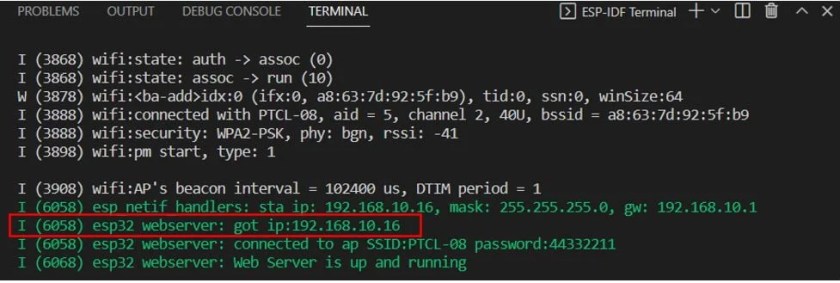
idf.py -p COMX flash monitorAfter the code flashes successfully, you can view all the informational logs. First, the station Wi-Fi is initialized. Then we can view the esp_netif_handlers which includes the IP, mask, and gw addresses. Then we get the log “got IP” followed by the ip address. We will use this IP address to access the web server.
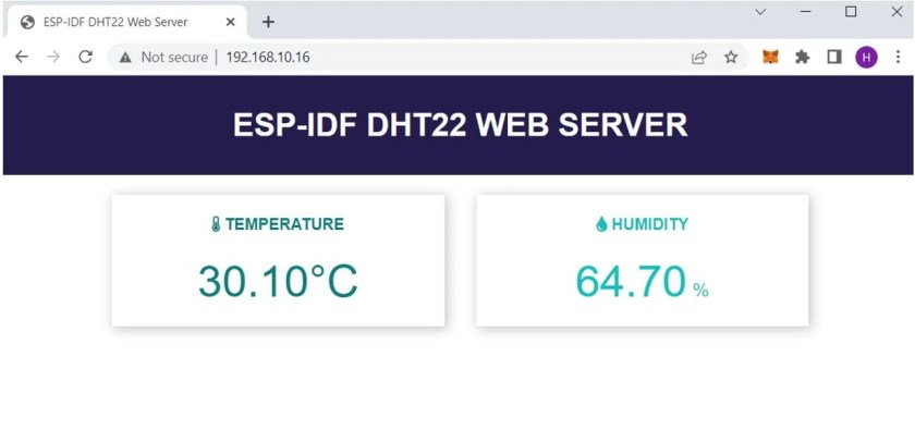
Open a new web browser and type the IP address that you obtained in the terminal, then press enter. The ESP32 DHT22 web server will open up showing the temperature and humidity readings that update after every few seconds.


You may like to read:
- ESP32 Web Server with ESP-IDF
- ESP32 BME280 Web Server ESP-IDF
- ESP32 DS18B20 Web Server ESP-IDF
- ESP32 BME680 Web Server ESP-IDF
If you are using Arduino IDE instead of ESP-IDF, you can refer to these articles:
- ESP32 DHT11 and DHT22 Web Server using Arduino IDE
- ESP32 DS18B20 Temperature Sensor Web Server with Arduino IDE
- BME280 Web Server with ESP32 (Arduino IDE)
- BME680 Web Server with ESP32 ( Arduino IDE)
We are a team of experienced Embedded Software Developers with skills in developing Embedded Linux, RTOS, and IoT products from scratch to deployment with a demonstrated history of working in the embedded software industry. Contact us for your projects: admin@esp32tutorials.com